
Installation Instructions


3299 Tower Drive
Newburgh, IN 47630
812.490.1525
www.MatrixTeam.com
11
Preliminary
//TODO enum protocol
uint16_t DataLength;
uint8_t Data[CAN_DATA_BYTES];
} CAN_frame_t;
USB
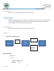
The CAN Bus interface of the proximity detection system must conform to ISO 11898 at the Physical Layer,
utilizing a “full CAN” implementation of the CAN 2.0B protocol, transmitting at 125 k baud, using 11 bit
identifiers. Cabling of the CAN Bus between the Proximity Detection System and FaceBoss will be Belden 3072F
cable (Joy P/N 100172283), or equivalent. There will be no provision internal to the Proximity Detection system
for the addition of the 120 ohm terminating resistor required for CAN communications. This resistor will be
added external to the system.
Wireless
The proximity detection system must be capable of providing a wireless access point. This access point may
utilize an external antenna connection
Wired
The proximity detection system must be capable of providing a 10/100BaseTX Ethernet connection (4-wire
Ethernet) via a secondary interface connection. The connection speed setting must be software configurable
between 10Mbps and 100Mbps.
Environmental Requirement
Operating Temperature Range: -10
o
C to +55
o
C
Power Supply
Power Supply Input Voltage: 72V and 24V
Note: If Power source uses AC line power: A line power filter is required to use for AC line emission noise suppressions.