GLK19264-7T-1U Technical Manual Revision: 1.
Contents Contents 1 2 3 4 5 ii Getting Started 1.1 Display Options Available 1.2 Accessories . . . . . . . . 1.3 Features . . . . . . . . . . 1.4 Connecting to a PC . . . . 1.5 Installing the Software . . 1.5.1 MOGD# . . . . . . . . . . . . . . . . . . . . . . . . . . . . . . . . . . . . . . . . . . . . . . . . . . . . . . . . . . . . . . . . . . . . . . . . . . . . . . . . . . . . . . . . . 1 1 1 4 4 5 5 Hardware Information 2.1 DB-9 Connector - For Non-USB modules only . . . . . . .
5.5 6 7 8 Set Box Space Mode . . . . . . . . . . . . . . . . . . . . . . . . . . . . . . . . . . . . . . Text 6.1 Introduction . . . . . . . . . . 6.1.1 Character Set . . . . . 6.1.2 Control Characters . . 6.2 Move Cursor Home . . . . . . 6.3 Setting the Cursor Position . . 6.4 Setting the Cursor Coordinate 6.5 Auto Scroll On . . . . . . . . 6.6 Auto Scroll Off . . . . . . . . 23 . . . . . . . . . . . . . . . . . . . . . . . . . . . . . . . . . . . . . . . . . . . . . . . . . . . . . . . . . .
11 Display Functions 11.1 Introduction . . . . . . . 11.2 Clear Screen . . . . . . . 11.3 Display On . . . . . . . 11.4 Display Off . . . . . . . 11.5 Set Brightness . . . . . . 11.6 Set and Save Brightness . 11.7 Set Contrast . . . . . . . 11.8 Set and Save Contrast . . . . . . . . . . . . . . . . . . . . . . . . . . . . . . . . . . . . . . . . . . . . . . . . . . . . . . . . . . . . . . . . . . . . . . . . . . . . . . . . . . . . . . . . . . . . . . . . . . . . . . . . . . . . . . . . . . .
15.11Miscellaneous . . . . . . . . . . . . . . . . . . . . . . . . . . . . . . . . . . . . . . . . . . 15.12Command By Number . . . . . . . . . . . . . . . . . . . . . . . . . . . . . . . . . . . . . 16 Appendix 16.1 Specifications . . . . . . . 16.1.1 Environmental . . 16.1.2 Electrical . . . . . 16.2 Optical Characteristics . . 16.3 Physical Layout . . . . . . 16.4 Ordering Information . . . 16.5 Definitions . . . . . . . . . 16.6 Contacting Matrix Orbital . 16.7 Revision History . . . . .
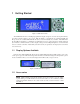
1 Getting Started Figure 1: GLK19264-7T-1U The GLK19264-7T-1U is an intelligent graphic LCD display designed to decrease development time by providing an instant solution to any project. With the ability to communicate via serial RS-232/TTL and I2 C protocols, the versatile GLK19264-7T-1U can be used with virtually any controller. The GLK192647T-1U-USB has the ability to communicate via USB.
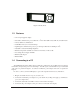
Figure 4: 5V Power Adapter Figure 3: Standard Power Matrix Orbital GLK19264-7T-1U 2
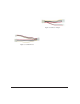
Figure 5: 3ft Mini-B USB Cable Figure 6: Breadboard Cable Figure 7: Communication & Power Cable Figure 8: Serial Cable Matrix Orbital GLK19264-7T-1U 3
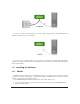
Figure 9: PC Bay Insert 1.
In order to connect your USB display to a personal computer simply plug the mini-B USB cable from the PC to the USB connector on the display. In order to power your USB display from a non-USB source simply plug the Power Cable Standard into the back of the display and the other end to a suitable power source. There is no communication through the Power Cable Standard. 1.5 Installing the Software 1.5.
3. Locate the file MogdSharp.zip on your desktop 4. Unzip MogdSharp.zip to a temporary directory using a program such as Winzip, Pkzip, etc. 5. Double click on "setup.exe" 6. Follow the instructions on the screen to complete the installation 7. MOGD# requires the .NET framework 2.0 and will download and install it automatically After the installation is complete there will be a Matrix Orbital entry under "Start->Programs->Matrix Orbital" in the start menu.
1 Power Cable Standard Connector 2 Power/Data Connector 3 DB9 Connector 4 Serial Header 5 Protocol Select Jumpers 6 Filesystem Lock Jumper Figure 11: GLK19264-7T-1U Non-USB 1 Power Cable Standard Connector 2 USB mini-B Connector 3 Protocol Select Jumpers 4 Filesystem Lock Jumper 5 Location for optional internal USB cable header* Figure 12: GLK19264-7T-1U USB NOTE * The USB module can have a header populated at your request to allow for an internal USB cable, talk to a Sales representitive for details.
2.1 DB-9 Connector - For Non-USB modules only The GLK19264-7T-1U provides a DB-9 Connector to readily interface with serial devices which use the EIA232 standard signal levels of ±30V. It is also possible to communicate at TTL levels of 0 to +5V by setting the Protocol Select Jumpers to TTL. As an added feature it is also possible to apply power through pin 9 of the DB-9 Connector in order to reduce cable clutter. However, in order to accomplish this you must set the Power Through DB-9 Jumper.
NOTE We do not recommend that you use pin 9 (Ring Indicator) of the PC to power the display module. You will have to make a special DB9 cable. WARNING Do not apply voltage through pin 9 of the DB-9 connector AND through the Power/Data Connector at the same time. 2.2 Power/Data Connector for Non-USB modules only The Power/Data Connector provides a standard connector for powering the display module. The GLK192647T-1U requires five volts for the standard display module.
Figure 16: Serial Header 2.4 Protocol Select Jumpers The Protocol Select Jumpers, pictured below in Figure 17, provide the means necessary to toggle the display module between RS-232, TTL and I2 C protocols. As a default for the Non-USB module, the jumpers are set to RS-232 mode with zero ohm resistors on the 232 jumpers.
Figure 18: Protocol-Select-Jumpers for GLK19264-7T-1U USB 2.5 Manual Override The Manual Override is provided to allow the GLK19264-7T-1U to be reset to some of the factory defaults. This can be particularly helpful if the display module has been set to an unknown baud rate or I2 C slave address and you are no longer able to communicate with it. If you wish to return the module to its default settings you must press the bottom left button at power up. Please see figure 19.
NOTE The display module will revert back to the old settings once turned off, unless the settings are saved. 2.6 Filesystem Lock Jumper The Filesystem Lock Jumper allows you to lock the filesystem on the GLK19264-7T-1U so that no fonts or bitmaps can be either written or deleted from the on board memory.
• Second, please ensure that the display module is set to communicate on the protocol that you are using, by checking the Protocol Select Jumpers. To change the protocol used by the display module see Section 2.4 on page 10. • Third, ensure that the host system and display module are both communicating on the same baud rate. The default baud rate for the display module is 19200 bps. • If you are communicating to the display via I2 C please ensure that the data is being sent to the correct address.
4 Communications 4.1 Introduction The commands listed in this chapter describe how to configure data flow on the GLK19264-7T-1U. 4.1.1 I2 C Communication Summary The GLK19264-7T-1U is capable of communicating at 100 KHz in I2 C mode, with 127 units addressable on a single I2 C communication line.
NOTE These delays are consrevative, and may be decreased based on performance 4.1.2 I2 C Transaction Example The typical I2 C transaction contains four parts: the start sequence, addressing, information, and stop sequence. To begin a transaction the data line, SDA, must toggle from high to low while the clock line, SCL, is high. Next, the display must be addressed using a one byte hexadecimal value, the default to write to the unit is 0x50, while read is 0x51.
4.2 Turn Flow Control On Syntax Parameters Description Hexadecimal Decimal ASCII Parameter full 0xFE 0x3A [full] [empty] 254 58 [full] [empty] 254 “:” [full] [empty] Length Description 1 Bytes remaining before issuing a almost full message. (Full is 0) empty 1 Bytes available before issuing a almost empty message. (Empty is 128) This command enables flow control.
Syntax Description Hexadecimal 0xFE 0x3B Decimal 254 59 ASCII 254 “;” This command turns off flow control. Bytes may overflow the buffer without warning. NOTE This command is not available in I2 C mode. Remembered 4.4 Yes Changing the I2 C Slave Address Syntax Parameters Description Hexadecimal Decimal ASCII Parameter adr 0xFE 0x33 [adr] 254 51 [adr] 254 “3” [adr] Length Description 1 The new I2 C write address (0x00 0xFF).
Description Remembered Default 4.6 This command sets the RS-232 port to the specified [speed]. The change takes place immediately. [speed] is a single byte specifying the desired port speed. Valid speeds are shown in the table below. The display module can be manually reset to 19,200 baud in the event of an error during transmission, including transmitting a value not listed below, by setting the manual override jumper during power up.
Examples Crystal Speed 16 Mhz Desired BAUD 13,500 speed = crystalspeed −1 8 ∗ DesiredBaud speed = 148.15 − 1 speed = 16, 000, 000 −1 8 ∗ 13, 500 speed = 147.15 • LSB = 0x93 (rounded) • MSB = 0x00 • Intended Baud Rate: 13,500 baud Actual Baud Rate: 16,000,000 =13,514 Percent Difference: 0.1% 8(147+1) NOTES • Results from the formula are rounded down to the nearest whole number (i.e 73.07 = 73). • This formula becomes less acurate as baud rates increase, due to rounding.
(b) Height (1 byte) (c) ASCII Start Value (1 byte) (d) ASCII End Value (1 byte) 2. Character Table (3 bytes for every character between the ASCII Start and End values inclusive) (a) High Offset MSB (1 byte) (b) Low Offset LSB(1 byte) (c) Character Width (1 byte) 3. Bitmap Data 5.1.2 Creating a Font The following is an example of how to create a font file for the letters h, i and j. First you must create the bitmaps containing the character data in bitmap form.
As you can see the letter h will take up five bytes with the last five bits being zero padded to form a full byte. So if you continue the process you will get the character data as seen in table 5.1.2. Character Data h i j 0x84 0x43 0x2D Character Data 0x2D 0x98 0xC6 0x24 0x84 0x98 0x19 0x60 0x20 Byte Size (For Reference) 0x05 0x03 0x04 The second part of the font file is the character table. The character table is comprised of three bytes for every glyph in the font file.
Syntax Parameters Description Hexadecimal Decimal ASCII Parameter refID 0xFE 0x24 [refID] [size] [data] 254 36 [refID] [size] [data] 254 “$” [refID] [size] [data] Length Description 1 A unique font identification number. size 2 Font file size (LSB to MSB). data x Font file data.
5.4 Font Metrics Syntax Parameters Description Remembered 5.5 Hexadecimal Decimal ASCII Parameter lm tm csp 0xFE 0x32 [lm] [tm] [csp] [lsp] [srow] 254 50 [lm] [tm] [csp] [lsp] [srow] 254 “2” [lm] [tm] [csp] [lsp] [srow] Length Description 1 Left margin: Location in pixels. 1 Top margin: Location in pixels. 1 Character Spacing: Amount of space in pixels between characters. lsp 1 Line Spacing: Amount of space between lines in pixels. srow 1 Scroll Row: The Y location of the last row in pixels.
6 6.1 Text Introduction The GLK19264-7T-1U is an intelligent display module, designed to reduce the amount of code necessary to begin displaying data. This means that it is able to display all ASCII formated characters and strings that are sent to it, which are defined in the current character set. The display module will begin displaying text at the top left corner of the display area, known as home, and continue to print to the display as if it was a page on a typewriter.
Parameters Description Remembered 6.4 Parameters Description Remembered Hexadecimal 0xFE 0x79 [x] [y] Decimal 254 121 [x] [y] ASCII 254 “y” [x] [y] Parameter Length Description x 1 The horizontal position in pixels. y 1 The vertical position in pixels. This command positions the insertion point at a specific pixel (X,Y), which references the top left corner of the font insertion point.
Syntax Description Remembered 7 7.1 Hexadecimal 0xFE 0x52 Decimal 254 82 ASCII 254 “R” When auto scrolling is disabled, text will wrap to the top left corner of the display area when the text reaches the end of the scroll row defined in the font metrics (the bottom right character position) see Section 5.4 on page 23. Existing text in the display area is not erased before new text is placed. A series of spaces followed by a “Cursor Home” command may be used to erase the top line of text.
Description The GLK19264-7T-1U is capable of storing 128 font and bitmap files up to 16 Kbytes total. In order to upload a bitmap to the GLK19264-7T-1U you must first initiate the upload font file command (0xFE 0x5E), you must then pass it a reference identification number, which must be unique for every font on the display module. You may then pass the display module the two byte file system size, which needs to be transfered LSB, then MSB.
Parameters Description Parameter Length Description X 1 Left bounds. Y 1 Top bounds. W 1 Width H 1 Height D (width*height)/8Data Drawing a bitmap to the GLK19264-7T-1U, without first uploading the image to the memory can be a very useful feature for drawing images that are not used very often.
8.3 Description This command sets the drawing color for subsequent graphic commands that do not have the drawing color passed as a parameter. The parameter [color] is the value of the color where white is 0 and black is 1-255. Remembered No Draw Pixel Syntax Parameters Description Remembered 8.4 No Drawing a Line Syntax Parameters Description Remembered 8.5 Hexadecimal 0xFE 0x70 [x] [y] Decimal 254 112 [x] [y] ASCII 254 “p” [x] [y] Parameter Length Description x 1 X screen location.
Syntax Parameters Description Remembered 8.6 No Draw a Rectangle Syntax Parameters Description Remembered 8.7 Hexadecimal 0xFE 0x65 [x] [y] Decimal 254 101 [x] [y] ASCII 254 “e” [x] [y] Parameter Length Description x 1 Left bounds. y 1 Top Bounds. This command will draw a line with the current drawing color from the last line end (x2,y2) to (x,y). This command uses the global drawing color.
8.8 Description This command draws a solid rectangle in the specified color (0: White, 1: Black). The top left corner is specified by (x1,y1) and the bottom right corner by (x2,y2). Since this command involves considerable processing overhead, we strongly recommend the use of flow control, particularly if the command is to be repeated frequently.
Syntax Parameters Description Remembered Hexadecimal Decimal ASCII Parameter ref 0xFE 0x69 [ref] [value] 254 105 [ref] [value] 254 “i” [ref] [value] Length Description 1 Initialized bar graph reference number. value 1 The number of pixels to fill. Once the bar graph has been initialized it can be filled in using this command. This command sets the bar graph specified by the [ref] number to fill in [value]. [value] is given in pixels and should not exceed the available height/width of the graph.
Description A strip chart is an area of the screen reserved for horizontal scrolling. This is normally used as follows: • Initialize the strip chart, which reserves the appropriate area of the screen. • Draw a line segment at the right or left side of the strip chart. • Shift the strip chart to the right or left. • Draw the next line segment. • Used this way the strip chart can produce a graph which scrolls smoothly horizontally in either direction. With text the strip chart can produce a marquis effect.
Description This command shifts the strip chart left or right. [ref] determines both which strip chart is used and which direction it will shift. The direction is selected by the most significant bit (MSB): • MSB: 0 shifts left • MSB: 1 shifts right For example if [ref] is 1: • 254 107 1 (hex FE 6B 01) shifts left • 254 107 129 (hex FE 6B 81) shifts right This command shifts the contents of the area defined in the Initialize Strip Chart command 8 pixels at a time. Remembered 9 9.
Table 33: LED 1 - top GPO2 GPO1 Yellow 0 0 Green 0 1 Red 1 0 Off 1 1 Table 34: LED 2 - middle GPO4 GPO3 Yellow 0 0 Green 0 1 Red 1 0 Off 1 1 Table 35: LED 3 - bottom GPO6 GPO5 Yellow 0 0 Green 0 1 Red 1 0 Off 1 1 9.2 General Purpose Output Off Syntax Parameters Description Hexadecimal 0xFE 0x56 [Num] Decimal 254 86 [Num] ASCII 254 “V” [Num] Parameter Length Description Num 1 GPO number. This command turns OFF general purpose output [num]. NOTE OFF means that the output is pulled LOW.
9.3 General Purpose Output On Syntax Parameters Description Hexadecimal 0xFE 0x57 [Num] Decimal 254 87 [Num] ASCII 254 “W” [Num] Parameter Length Description Num 1 GPO number. This command turns ON general purpose output [num]. The standard GPO’s on the GLK19264-7T-1U output 20mA of current at 5V. NOTE ON means the output is pulled HIGH. Remembered 9.
Table 39: Keypad Values up arrow 0x42 down arrow 0x48 left arrow 0x44 right arrow 0x43 center 0x45 top left 0x41 bottom left 0x47 NOTE Please note that keypads may be laid out in a different pattern. If this is the case, the user will need to interpret the key codes differently. Also included are two extra pins on each end of the connector to be used for ground strapping. This can be used in conjunction with your keypad if a ground strap connection is required or if a common ground connection is needed.
10.4 Poll Key Press Syntax Description Remembered Hexadecimal 0xFE 0x26 Decimal 254 38 ASCII 254 “&” This command returns any buffered key presses via the serial interface. The host system must be set up to receive key codes. When the display receives this command, it will immediately return any buffered key presses which may have not been read already. If there is more than one key press buffered, then the high order bit (MSB) of the returned key code will be set (1).
Description This command sets the time between key press and key read. All key types with the exception of latched piezo switches will ’bounce’ for a varying time, depending on their physical characteristics. The [time] value is in increments of 6.554ms. The default debounce time for the module is 8 (about 52ms), which is adequate for most membrane keypads. Remembered Default Yes 8 10.
Examples When the key code associated with key ’P’ (0x50) is pressed, the release code is ’p’ (0x70). In RS-232 polled mode or via the I2 C, the “Key Down / Key Up” codes are used; however, the user should be careful of timing details. If the poll rate is slower than the simulated auto-repeat it is possible that polling for a key up code will be delayed long enough for an unwanted key repeat to be generated. 10.
Description This command will allow you to reassign the key codes that correspond to the key presses on the matrix style key pad. The first 9 bytes that are transmitted will be used for the key down codes and the next 9 bytes that are transmitted will be used for the key up codes.
Syntax Description Remembered Hexadecimal 0xFE 0x58 Decimal 254 88 ASCII 254 “X” This command clears the display and resets the text insertion position to the top left position of the screen defined in the font metrics. No 11.3 Display On Syntax Parameters Description Remembered Default Hexadecimal Decimal ASCII Parameter min 0xFE 0x42 [min] 254 66 [min] 254 “B” [min] Length Description 1 Minutes before turning the display on (0 to 90).
Description This command sets the display [brightness]. If the remember function is on, this command acts the same as ’Set and Save Brightness’. Remembered Default Yes 255 11.6 Set and Save Brightness Description Hexadecimal 0xFE 0x98 [brightness] Decimal 254 152 [brightness] Parameter Length Description brightness 1 Backlight setting (0 to 255). This command sets and saves the display [brightness] as default. Remembered Always Syntax Parameters 11.
11.8 Set and Save Contrast Syntax Parameters Description Hexadecimal 0xFE 0x91 [contrast] Decimal 254 145 [contrast] Parameter Length Description contrast 1 Contrast value (0 to 255). This command sets the display’s contrast to [contrast], where [contrast] is a value between 0x00 and 0xFF (between 0 to 255). Lower values cause ‘on’ elements in the display area to appear lighter, while higher values cause ‘on’ elements to appear darker.
Host 0xFE 0x24 0x01 0x19 0x00 Display 0x01 0x01 0x05 0x05 0x01 0x07 0x07 0x01 0x49 0x49 0x01 ... 0x60 ... 0x60 0x01 Comments Command Prefix Upload Font File Command Reference ID Size (LSB) Size (MSB) Confirmation Byte Confimation Byte Font Width Echo Font Width Confimation Byte Font Height Echo Font Height Confimation Byte Font ASCII Start Value Echo Font ASCII Start Value Confimation Byte ...
NOTES • The GLK19264-7T-1U has watch dog timer, set to 2.1 seconds in between transmissions, in order prevent the display module from staying in a waiting state. • Once the timeout has been reached the timer will reset the display and issue a 0xFE 0xD4 response to the host to signal that this has happened. 12.1.2 XModem Upload Protocol In addition to its original simple upload format, Matrix Orbital has added an XModem based protocol.
Host 0xFE 0xDB 0x85 0x06 0x30 0x00 0x40 0x00 0x00 Display 0x06 0x01 0x80 0x7F 0x06 <128 bytes> 0x1E 0x47 0x06 0x7F 0x80 0x06 <128 bytes> 0x5A 0x0D ... 0x04 0x06 ...
Syntax Description Hexadecimal 0xFE 0x21 0x59 0x21 Decimal 254 33 89 33 ASCII 254 “!” “Y” “!” This command completely erases the display’s non-volatile memory. It removes all fonts, font metrics, bitmaps, and settings (current font, cursor position, communication speed, etc.). It is an “odd” command in that it is three bytes in length in order to prevent accidental execution. NOTE After deleting the file system it is important to cycle power to your display to ensure the removal process is completed.
12.5 Get Filesystem Directory Syntax Description Hexadecimal 0xFE 0xB3 Decimal 254 179 This command will return a directory of the contents of the file system. The first byte returned will be a hex value representing the number of entries in the filesystem, followed by four bytes for each entry.
Syntax Parameters Description Remembered Hexadecimal 0xFE 0xB2 [Type] [refID] Decimal 254 178 [Type] [refID] Parameter Length Description Type 1 File type (0:Font File, 1:Bitmap) refID 1 Reference ID number Download a specified file from the filesystem. The first 4 bytes will be the length of the file (LSB to MSB) followed by 2 bytes representing the width and height of the image then the data contained in the file. No 12.
13.2 Set Remember Syntax Parameters Description Hexadecimal 0xFE 0x93 [switch] Decimal 254 147 [switch] Parameter Length Description switch 1 0: Do not remember, 1: Remember This command allows you to switch the remember function on and off. To use the remember function, set remember to on, then set all of the settings that you wish to save, settings that are listed as ’Remember: Yes’ support being saved into the non-volatile memory.
Description Paranoia allows you to lock the module from displaying information, as well as enables the protection of the filesystem and module settings.
13.4 Set and Save Data Lock Syntax Parameters Description Remembered Default Hexadecimal 0xFE 0xCB 0xF5 0xA0 [level] Decimal 254 203 245 160 [level] Parameter Length Description level 1 Sets the data lock level This command will set and save the data lock level. See the Data Lock section for more information. Always 0 13.5 Dump the Filesystem Syntax Description Remembered Hexadecimal 0xFE 0x30 Decimal 254 48 ASCII 254 “0” This will allow you to dump the filesystem for debugging purposes.
14 Description Reads whatever was written by Write Customer Data. Remembered No Miscellaneous 14.1 Introduction This chapter covers the ’Report Version Number’ and ’Read Module Type’ commands. These commands can be particularly useful to find out more information about the display module before contacting technical support. 14.
Description Remembered Matrix Orbital This command will return a hex value corresponding to the the model number of the module see the following table: Hex 1 5 7 9 B D F 13 15 21 23 25 27 29 2B 31 33 35 37 39 3B 3D 3F 41 43 45 47 49 4B 4D 4F 51 53 55 57 5B 71 73 77 79 No Product ID LCD0821 LCD2041 LCD4041 LK204-25 VFD2021 VFD4021 VK204-25 GLC24064 GLK24064-25 Unused Unused GLK24064-16-1U-USB GLK19264-7T-1U-USB GLK12232-16-SM LK204-7T-1U LK404-AT LK402-12 LK204-25PC VK202-24-USB VK204-24-USB VK162-12 PK2
15 Command Summary 15.
Description Setting the Cursor Position Setting the Cursor Coordinate Auto Scroll On Auto Scroll Off Syntax Hexadecimal Decimal ASCII Hexadecimal Decimal ASCII Hexadecimal Decimal ASCII Hexadecimal Decimal ASCII 0xFE 0x47 [col] [row] 254 71 [col] [row] 254 “G” [col] [row] 0xFE 0x79 [x] [y] 254 121 [x] [y] 254 “y” [x] [y] 0xFE 0x51 254 81 254 “Q” 0xFE 0x52 254 82 254 “R” Syntax Hexadecimal Decimal ASCII Hexadecimal Decimal ASCII Hexadecimal Decimal ASCII 0xFE 0x5E [refID] [size] [data] 254 94 [refID] [s
Description Draw a Rectangle Drawing a Solid Rectangle Initializing a Bar Graph Drawing a Bar Graph Initializing a Strip Chart Shifting a Strip Chart Syntax Hexadecimal Decimal ASCII Hexadecimal Decimal ASCII Hexadecimal Decimal ASCII Hexadecimal Decimal ASCII Hexadecimal Decimal ASCII Hexadecimal Decimal ASCII 0xFE 0x72 [color] [x1] [y1] [x2] [y2] 254 114 [color] [x1] [y1] [x2] [y2] 254 “r” [color] [x1] [y1] [x2] [y2] 0xFE 0x78 [color] [x1] [y1] [x2] [y2] 254 120 [color] [x1] [y1] [x2] [y2] 254 “x” [
Description Clear Key Buffer Set Debounce Time Set Auto Repeat Mode Auto Repeat Mode Off Assign Keypad Codes Syntax Hexadecimal Decimal ASCII Hexadecimal Decimal ASCII Hexadecimal Decimal ASCII Hexadecimal Decimal ASCII Hexadecimal Decimal 0xFE 0x45 254 69 254 “E” 0xFE 0x55 [time] 254 85 [time] 254 “U” [time] 0xFE 0x7E [mode] 254 126 [mode] 254 “~” [mode] 0xFE 0x60 254 96 254 “‘” 0xFE 0xD5 [KDown] [KUp] 254 213 [KDown] [KUp] Page 38 38 39 40 40 15.
Description Deleting a File Get Filesystem Space Get Filesystem Directory Filesystem Upload Downloading a File Moving a File Syntax Hexadecimal Decimal Hexadecimal Decimal Hexadecimal Decimal Hexadecimal Decimal Hexadecimal Decimal Hexadecimal Decimal 0xFE 0xAD [type] [refID] 254 173 [type] [refID] 0xFE 0xAF 254 175 0xFE 0xB3 254 179 0xFE 0xB0 [Size] [Data] 254 176 [Size] [Data] 0xFE 0xB2 [Type] [refID] 254 178 [Type] [refID] 0xFE 0xB4 [oldT] [oldID] [newT] [newID] 254 180 [oldT] [oldID] [newT] [newID] S
15.
Command Hex 0x78 0x79 0x7E 0x91 0x93 0x98 0x99 0xA4 0xAC 0xAD 0xAF 0xB0 0xB2 0xB3 0xB4 0xC3 0xCA 16 Description Page Dec ASCII 120 “x” 121 “y” 126 “~” 145 147 152 153 164 172 173 175 176 178 179 180 195 202 Drawing a Solid Rectangle Setting the Cursor Coordinate Set Auto Repeat Mode Set and Save Contrast Set Remember Set and Save Brightness Set Brightness Setting a Non-Standard Baud Rate Set Box Space Mode Deleting a File Get Filesystem Space Filesystem Upload Downloading a File Get Filesystem Directory
16.1.2 Electrical Table 85: Electrical Specifications Standard -LV Supply Voltage +5Vdc ±0.25V +3.3Vdc ±0.25V Minimum Current 55mA typical USB Version add 10mA (65mA) typical Backlight On (YG) add 25mA (80mA) typical Backlight On (GW & WB) add 40mA (95/105mA) typical GPO (onboard LEDs) add up to 10mA each GPO (external) add up to 20mA each 16.
Figure 24: Physical Diagram NOTE cation.
G 1 L 2 K 3 192 4 64 5 -7T 6 -1U 7 -USB 8 -YG 9 10 -E 11 Table 87: Part Numbering Scheme # 1 2 3 4 5 6 7 Description Screen Type Display Technology Input Interface Width Height Keypad Buttons Form Factor 8 Protocol 9 Colour (Text/Background) 10 Input Voltage 11 Temperature Options G: Graphic L: Liquid Crystal Display K: Keypad 192: Pixel Width Count 64: Pixel Height Count -7T: Seven Integrated Tactile Keys -1U: Fits a 1U Opening NP: Standard RS232/TTL/I2C -USB: Universal Serial Bus Onl
16.4 Ordering Information 16.5 Definitions E Extended Temperature (-20C to 70C) LV Low Voltage (+3.3V DC) GW White Backlight (Grey text on White Background) WB White Backlight (White text on Blue Background) YG Yellow Green Backlight with Grey text MSB Most Significant Byte LSB Least Significant Byte 16.6 Contacting Matrix Orbital Telephone Sales: 1(403)229-2737 Support: 1(403)204-3750 On The Web Sales: http://www.MatrixOrbital.com Support: http://www.MatrixOrbital.ca Forums: http://www.lcdforums.com 16.