GLK240128-25 Technical Manual Revision: 1.
Contents Contents 1 2 3 4 5 ii Getting Started 1.1 Display Options Available 1.2 Accessories . . . . . . . . 1.3 Features . . . . . . . . . . 1.4 Connecting to a PC . . . . 1.5 Installing the Software . . 1.5.1 MOGD# . . . . . . . . . . . . . . . . . . . . . . . . . . . . . . . . . . . . . . . . . . . . . . . . . . . . . . . . . . . . . . . . . . . . . . . . . . . . . . . . . . . . . . . . . . . . . . . . . . . . . . . . . . . . . . . . . . . . . . . . . . . . . . . . . . . . . .
6 7 8 9 Text 6.1 Introduction . . . . . . . . . . 6.1.1 Character Set . . . . . 6.1.2 Control Characters . . 6.2 Move Cursor Home . . . . . . 6.3 Setting the Cursor Position . . 6.4 Setting the Cursor Coordinate 6.5 Auto Scroll On . . . . . . . . 6.6 Auto Scroll Off . . . . . . . . . . . . . . . . . . . . . . . . . . . . . . . . . . . . . . . . . . . . . . . . . . . . . . . . . . . . . . . . . . . . . . . . . . . . . . . . . . . . . . . . . . . . . . . . . . . . . . . . . . . . . . . . . .
10.5 10.6 10.7 10.8 Set Brightness . . . . . . Set and Save Brightness . Set Contrast . . . . . . . Set and Save Contrast . . . . . . . . . . . . . . . . . . . . . . . . . . . . . . . . . . . . . . . . . . . . . . . . . . . . . . . . . . . . . . . . . . . . . . . . . . . . . . . . . . . . . . . . . . . . . . . . . . . . . . . . . . . . . . . . . . . . . . . . . . . . . . . . . . 39 39 39 40 11 Filesystem 11.1 Introduction . . . . . . . . . . . . 11.1.
15 Appendix 15.1 Specifications . . . . . . . 15.1.1 Environmental . . 15.1.2 Electrical . . . . . 15.2 Physical Layout . . . . . . 15.3 Ordering Information . . . 15.4 Definitions . . . . . . . . . 15.5 Contacting Matrix Orbital . 15.6 Revision History . . . . . Matrix Orbital . . . . . . . . . . . . . . . . . . . . . . . . . . . . . . . . . . . . . . . . . . . . . . . . . . . . . . . . . . . . . . . . . . . . . . . . . . . . . . . . . . . . . . . . . . . . . . . . . . . . . . . .
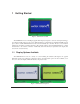
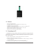
1 Getting Started Figure 1: GLK240128-25-WB The GLK240128-25 is an intelligent graphic LCD display designed to decrease development time by providing an instant solution to any project. With the ability to communicate via serial RS-232/TTL and I2 C protocols, the versatile GLK240128-25 can be used with virtually any controller. The ease of use is further enhanced by an intuitive command structure to allow display settings such as backlight brightness, contrast and baud rate to be software controlled.
1.2 Accessories NOTE Matrix Orbital provides all the interface accessories needed to get your display up and running. You will find these accessories and others on our e-commerce website at http://www.matrixorbital.com. To contact a sales associate see Section 15.5 on page 61 for contact information.
Figure 8: 4X4 Keypad 1.3 • • • • • • • • 1.
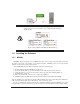
WARNING DO NOT use the standard floppy drive power connector, as this will not provide you with the correct voltage and will damage the display module. Figure 9: PC vs Matrix Orbital Display Module Wiring 1.5 Installing the Software 1.5.1 MOGD# MOGD# is the latest updated version of MOGD and can be used to manage font and graphics downloads as well as exercise all of the features of our graphical displays. MOGD# provides a new user friendly interface as well as many feature enhancements.
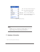
Port The serial port the display is plugged in to. Speed The communication speed the display module is set to. (Default 19,200) Display Type The type of display. (GLK240128-25) PCB Revision The revision of the display you are using. (Found on the back of the PCB) Figure 10: Mogd Sharp Settings NOTES • MOGD# may also be downloaded from Matrix Orbital’s support site at http://www.matrixorbital.ca/software/software_graphic/MogdSharp • Winzip is available as a free download from http://www.winzip.
1 DB-9 Connector 2 Power Through DB9 Jumper 3 Manual Override 4 Keypad Interface Connector 5 Power / Data Connector 6 File System Lock Jumper Figure 11: GLK240128-25 2.1 DB-9 Connector The GLK240128-25 provides a DB-9 Connector to readily interface with serial devices which use the EIA232 standard signal levels of ±12V to ±12V. It is also possible to communicate at TTL levels of 0 to +5V by setting the Protocol Select Jumpers to TTL.
Pin 2 Pin 3 Pin 5 Pin 9 Tx \ SDA (I2 C data) Rx \ SCL (I2 C clock) GND PWR (Must solder Power Through DB9 Jumper. See table ?? on page ?? for power requirements.) Figure 12: RS-232 Pin-out 2.1.1 Power Through DB-9 Jumper In order to provide power through pin 9 of the DB-9 Connector you must place a solder jumper on the Power through DB-9 Jumper pictured in figure 13 below.
WARNING Do not apply voltage through pin 9 of the DB-9 connector AND through the Power/Data Connector at the same time. 2.2 Power/Data Connector The Power/Data Connector provides a standard connector for powering the display module. The GLK24012825 requires five volts for the standard display module, between nine to fifteen for the wide voltage (V) and between nine to thirty-five volts for the wide voltage with efficient power supply module (VPT).
2.3 Protocol Select Jumpers The Protocol Select Jumpers, pictured below in figure 15, provide the means necessary to toggle the display module between RS-232, TTL and I2 C protocols. As a default, the jumpers are set to RS-232 mode with zero ohm resistors on the 232 jumpers. In order to place the display module in I2 C mode you must first remove the zero ohm resistors from the 232 jumpers and then solder the resistors on to the I2C jumpers.
Figure 16: Keypad Interface Connector 2.5 Manual Override Manual Override is provided to allow the GLK240128-25 to be reset to factory defaults. This can be particularly helpful if the display module has been set to an unknown baud rate or I2 C Slave Address and you are no longer able to communicate with it. If you wish to return the module to its default settings you must: 1. 2. 3. 4. 5. Power off the display module. Place a jump between Row 5 and Column 1. Power up the display module.
Table 1: Default Values Contrast 128 Backlight 255 Baud Rate 19.2 kbps I2 C Slave Address 0x50 Data Lock False RS232AutoTransmitData True NOTE The display module will revert back to the old settings once turned off, unless the settings are saved. 2.6 Filesystem Lock Jumper The Filesystem Lock Jumper allows you to lock the filesystem on the GLK240128-25 so that no fonts or bitmaps can be either written or deleted from the on board memory.
3 Troubleshooting 3.1 The display does not turn on when power is applied. • First, you will want to make sure that you are using the correct power connector. Standard floppy drive power cables from your PC power supply may fit on the Power/Data Connector however they do not have the correct pin-out as can be seen in figure 9 on page 4. Matrix Orbital supplies power cable adapters for connecting to a PC, which can be found in the Accessories Section on page 2.
3.4 There is a problem uploading fonts or bitmaps. • First, ensure that you can communicate to the display. A good test is to use a PC, with MOGD# installed, to connect to the display. See Section 1.4 on page 3 for setting up a PC to test the GLK24012825. • Second, unsure that the Filesystem Lock Jumper has not been set. See Section 2.6 on page 11. • Third, please ensure that the display module’s memory is not full. The GLK240128-25 has 16 Kb of memory for fonts and bitmaps.
followed by an ACK to indicate that the master still needs data, and a NAK to indicate that the transmission is over. The has some speed limitations, especially when run in I2 C mode. Here are some considerations when writing I2 C code: * to be able to read the replies of query commands (eg.
4.2 Turn Flow Control On Syntax Parameters Description Hexadecimal Decimal ASCII Parameter full 0xFE 0x3A [full] [empty] 254 58 [full] [empty] 254 “:” [full] [empty] Length Description 1 Bytes remaining before issuing a almost full message. (Full is 0) empty 1 Bytes available before issuing a almost empty message. (Empty is 128) This command enables flow control.
Syntax Description Hexadecimal 0xFE 0x3B Decimal 254 59 ASCII 254 “;” This command turns off flow control. Bytes may overflow the buffer without warning. NOTE This command is not available in I2 C mode. Remembered 4.4 Yes Changing the I2 C Slave Address Syntax Parameters Description Hexadecimal Decimal ASCII Parameter adr 0xFE 0x33 [adr] 254 51 [adr] 254 “3” [adr] Length Description 1 The new I2 C write address (0x00 0xFF).
Description This command sets the RS-232 port to the specified [speed]. The change takes place immediately. [speed] is a single byte specifying the desired port speed. Valid speeds are shown in the table below. The display module can be manually reset to 19,200 baud in the event of an error during transmission, including transmitting a value not listed below, by setting the manual override jumper during power up.
Examples Crystal Speed 16 Mhz Desired BAUD 13,500 speed = crystalspeed −1 8 ∗ DesiredBaud speed = 148.15 − 1 speed = 16, 000, 000 −1 8 ∗ 13, 500 speed = 147.15 • LSB = 0x93 (rounded) • MSB = 0x00 • Intended Baud Rate: 13,500 baud Actual Baud Rate: 16,000,000 =13,514 Percent Difference: 0.1% 8(147+1) NOTES • Results from the formula are rounded down to the nearest whole number (i.e 73.07 = 73). • This formula becomes less acurate as baud rates increase, due to rounding.
5.1.1 Font File Format A font file consists of three parts, a header, a character table and bitmap data. 1. Header (4 bytes) (a) (b) (c) (d) Nominal Width (1 byte) Height (1 byte) ASCII Start Value (1 byte) ASCII End Value (1 byte) 2. Character Table (3 bytes for every character between the ASCII Start and End values inclusive) (a) High Offset MSB (1 byte) (b) Low Offset LSB(1 byte) (c) Character Width (1 byte) 3. Bitmap Data 5.1.
1 1 1 1 1 1 1 Bitmap Data 0 0 0 0 0 0 0 1 1 1 0 0 0 0 0 0 0 0 0 0 0 0 0 0 1 1 1 1 Byte Hex Value 10000100 00101101 10011000 11000110 00100000 0x84 0x2D 0x98 0xC6 0x20 Figure 20: Bitmap Encoding As you can see the letter h will take up five bytes with the last five bits being zero padded to form a full byte. So if you continue the process you will get the character data as seen in table 5.1.2.
0x05 0x12 0xC6 0x60 0x07 0x03 0x20 Table 10: Sample Font File 0x68 0x6A 0x00 0x0D 0x00 0x15 0x04 0x84 0x43 0x24 0x84 0x2D 0x05 0x2D 0x98 0x00 0x98 0x19 Red = Header Blue = Character Table Purple = Character Data 5.2 Uploading a Font File Syntax Parameters Description Hexadecimal Decimal ASCII Parameter refID 0xFE 0x24 [refID] [size] [data] 254 36 [refID] [size] [data] 254 “$” [refID] [size] [data] Length Description 1 A unique font identification number. size 2 Font file size (LSB to MSB).
5.4 Description In order to set the font on the you must know the font identification number of the font that you wish to use. The font ID is established when the font is saved to the display. The default installed fonts are “Small Filled” and “Futura Bk BT 16” and their font ID’s are 0x01 and 0x02 respectfully, with “Small Filled” being the default selected font.
Description Parameter Length Description value 1 Value (0: Off, 1: On) This command will toggle the box space mode. Box space mode is when a box, the size of the character to be written, is printed to the display before a character is written. Remembered Default Yes On Parameters 6 Text 6.1 Introduction The is an intelligent display module, designed to reduce the amount of code necessary to begin displaying data.
6.3 Setting the Cursor Position Description Hexadecimal 0xFE 0x47 [col] [row] Decimal 254 71 [col] [row] ASCII 254 “G” [col] [row] Parameter Length Description col 1 Column row 1 Row This command sets the text insertion point to the [col] and [row] specified. The insertion point is positioned using the base size of the current font (this command does not position the insertion point at a specific pixel).
Default 6.6 Auto Scroll Off Syntax Description Remembered 7 7.1 On Hexadecimal 0xFE 0x52 Decimal 254 82 ASCII 254 “R” When auto scrolling is disabled, text will wrap to the top left corner of the display area when the text reaches the end of the scroll row defined in the font metrics (the bottom right character position) see Section 5.4 on page 22. Existing text in the display area is not erased before new text is placed.
Description The is capable of storing 128 font and bitmap files up to 16 Kbytes total. In order to upload a bitmap to the you must first initiate the upload font file command (0xFE 0x5E), you must then pass it a reference identification number, which must be unique for every font on the display module. You may then pass the display module the two byte file system size, which needs to be transfered LSB, then MSB. This is almost always the entire 16kB, meaning the values 0x00 0x40 0x00 0x00 must be issued.
Parameters Description Parameter Length Description X 1 Left bounds. Y 1 Top bounds. W 1 Width H 1 Height D (width*height)/8Data Drawing a bitmap to the , without first uploading the image to the memory can be a very useful feature for drawing images that are not used very often.
8.3 Description This command sets the drawing color for subsequent graphic commands that do not have the drawing color passed as a parameter. The parameter [color] is the value of the color where white is 0 and black is 1-255. Remembered No Draw Pixel Syntax Parameters Description Remembered 8.4 No Drawing a Line Syntax Parameters Description Remembered 8.5 Hexadecimal 0xFE 0x70 [x] [y] Decimal 254 112 [x] [y] ASCII 254 “p” [x] [y] Parameter Length Description x 1 X screen location.
Syntax Parameters Description Remembered 8.6 No Draw a Rectangle Syntax Parameters Description Remembered 8.7 Hexadecimal 0xFE 0x65 [x] [y] Decimal 254 101 [x] [y] ASCII 254 “e” [x] [y] Parameter Length Description x 1 Left bounds. y 1 Top Bounds. This command will draw a line with the current drawing color from the last line end (x2,y2) to (x,y). This command uses the global drawing color.
8.8 Description This command draws a solid rectangle in the specified color (0: White, 1: Black). The top left corner is specified by (x1,y1) and the bottom right corner by (x2,y2). Since this command involves considerable processing overhead, we strongly recommend the use of flow control, particularly if the command is to be repeated frequently.
Syntax Parameters Description Remembered Hexadecimal Decimal ASCII Parameter ref 0xFE 0x69 [ref] [value] 254 105 [ref] [value] 254 “i” [ref] [value] Length Description 1 Initialized bar graph reference number. value 1 The number of pixels to fill. Once the bar graph has been initialized it can be filled in using this command. This command sets the bar graph specified by the [ref] number to fill in [value]. [value] is given in pixels and should not exceed the available height/width of the graph.
Description A strip chart is an area of the screen reserved for horizontal scrolling. This is normally used as follows: • Initialize the strip chart, which reserves the appropriate area of the screen. • Draw a line segment at the right or left side of the strip chart. • Shift the strip chart to the right or left. • Draw the next line segment. • Used this way the strip chart can produce a graph which scrolls smoothly horizontally in either direction. With text the strip chart can produce a marquis effect.
Description This command shifts the strip chart left or right. [ref] determines both which strip chart is used and which direction it will shift. The direction is selected by the most significant bit (MSB): • MSB: 0 shifts left • MSB: 1 shifts right For example if [ref] is 1: • 254 107 1 (hex FE 6B 01) shifts left • 254 107 129 (hex FE 6B 81) shifts right This command shifts the contents of the area defined in the Initialize Strip Chart command 8 pixels at a time. Remembered 9 9.
9.2 Auto Transmit Key Presses On Syntax Description Hexadecimal 0xFE 0x41 Decimal 254 65 ASCII 254 “A” In this mode, all key presses are sent immediately to the host system without the use of the poll keypad command. This is the default mode on power up. NOTE This command is not available in I2 C. Remembered Default 9.
Description This command returns any buffered key presses via the serial interface. The host system must be set up to receive key codes. When the display receives this command, it will immediately return any buffered key presses which may have not been read already. If there is more than one key press buffered, then the high order bit (MSB) of the returned key code will be set (1). If this is the only buffered key press, then the MSB will be cleared (0).
9.7 Description This command sets the time between key press and key read. All key types with the exception of latched piezo switches will ’bounce’ for a varying time, depending on their physical characteristics. The [time] value is in increments of 6.554ms. The default debounce time for the module is 8 (about 52ms), which is adequate for most membrane keypads.
Examples 9.8 Auto Repeat Mode Off Description Hexadecimal 0xFE 0x60 Decimal 254 96 ASCII 254 “‘” This command turns auto repeat mode off. See Set Auto Repeat Mode. Remembered No Syntax 9.9 When the key code associated with key ’P’ (0x50) is pressed, the release code is ’p’ (0x70). In RS-232 polled mode or via the I2 C, the “Key Down / Key Up” codes are used; however, the user should be careful of timing details.
10 Display Functions 10.1 Introduction The employs software controlled display settings, which allow for control over, clearing the screen, changing the brightness and contrast or setting timers for turning it on or off. The combination of these allow you complete software control over your display’s appearance. 10.
Description This command turns the backlight off immediately. The backlight will remain off until a ’Display On’ command has been received. Remembered Yes 10.5 Set Brightness Syntax Parameters Description Remembered Default Hexadecimal Decimal Parameter brightness 0xFE 0x99 [brightness] 254 153 [brightness] Length Description 1 Display brightness setting (0 to 255). This command sets the display [brightness]. If the remember function is on, this command acts the same as ’Set and Save Brightness’.
Description This command sets the display’s contrast to [contrast], where [contrast] is a value between 0x00 and 0xFF (between 0 to 255). Lower values cause ‘on’ elements in the display area to appear lighter, while higher values cause ‘on’ elements to appear darker. Lighting and temperature conditions will affect the actual value used for optimal viewing. Individual display modules will also differ slightly from each other in appearance.
11 Filesystem 11.1 Introduction The incorporates a 16 Kbyte on board flash memory in order to allow up to 128 font and bitmap files to be transfered directly onto the display and recalled whenever necessary. The filesystem can address font and bitmap files combined up to 16 Kbytes. It is recommended that fonts and bitmaps are uploaded when possible all together after a filesystem wipe ro preserve memory integrity. These fonts and bitmaps can then be locked to ensure they remain intact.
Host 0xFE 0x24 0x01 0x19 0x00 Display 0x01 0x01 0x05 0x05 0x01 0x07 0x07 0x01 0x49 0x49 0x01 ... 0x60 ... 0x60 0x01 Comments Command Prefix Upload Font File Command Reference ID Size (LSB) Size (MSB) Confirmation Byte Confimation Byte Font Width Echo Font Width Confimation Byte Font Height Echo Font Height Confimation Byte Font ASCII Start Value Echo Font ASCII Start Value Confimation Byte ...
NOTES • The has watch dog timer, set to 2.1 seconds in between transmissions, in order prevent the display module from staying in a waiting state. • Once the timeout has been reached the timer will reset the display and issue a 0xFE 0xD4 response to the host to signal that this has happened. 11.1.2 XModem Upload Protocol In addition to its original simple upload format, Matrix Orbital has added an XModem based protocol.
Host 0xFE 0xDB 0x85 0x06 0x30 0x00 0x40 0x00 0x00 Display 0x06 0x01 0x80 0x7F 0x06 <128 bytes> 0x1E 0x47 0x06 0x7F 0x80 0x06 <128 bytes> 0x5A 0x0D ... 0x04 0x06 ...
Syntax Description Hexadecimal 0xFE 0x21 0x59 0x21 Decimal 254 33 89 33 ASCII 254 “!” “Y” “!” This command completely erases the display’s non-volatile memory. It removes all fonts, font metrics, bitmaps, and settings (current font, cursor position, communication speed, etc.). It is an “odd” command in that it is three bytes in length in order to prevent accidental execution. NOTE After deleting the file system it is important to cycle power to your display to ensure the removal process is completed.
11.5 Get Filesystem Directory Syntax Description Hexadecimal 0xFE 0xB3 Decimal 254 179 This command will return a directory of the contents of the file system. The first byte returned will be a hex value representing the number of entries in the filesystem, followed by four bytes for each entry.
Syntax Parameters Description Remembered Hexadecimal 0xFE 0xB2 [Type] [refID] Decimal 254 178 [Type] [refID] Parameter Length Description Type 1 File type (0:Font File, 1:Bitmap) refID 1 Reference ID number Download a specified file from the filesystem. The first 4 bytes will be the length of the file (LSB to MSB) followed by 2 bytes representing the width and height of the image then the data contained in the file. No 11.
12.2 Set Remember Syntax Parameters Description Hexadecimal 0xFE 0x93 [switch] Decimal 254 147 [switch] Parameter Length Description switch 1 0: Do not remember, 1: Remember This command allows you to switch the remember function on and off. To use the remember function, set remember to on, then set all of the settings that you wish to save, settings that are listed as ’Remember: Yes’ support being saved into the non-volatile memory.
Description Paranoia allows you to lock the module from displaying information, as well as enables the protection of the filesystem and module settings.
12.4 Set and Save Data Lock Syntax Parameters Description Remembered Default Hexadecimal 0xFE 0xCB 0xF5 0xA0 [level] Decimal 254 203 245 160 [level] Parameter Length Description level 1 Sets the data lock level This command will set and save the data lock level. See the Data Lock section for more information. Always 0 12.5 Dump the Filesystem Syntax Description Remembered Hexadecimal 0xFE 0x30 Decimal 254 48 ASCII 254 “0” This will allow you to dump the filesystem for debugging purposes.
13 Description Reads whatever was written by Write Customer Data. Remembered No Miscellaneous 13.1 Introduction This chapter covers the ’Report Version Number’ and ’Read Module Type’ commands. These commands can be particularly useful to find out more information about the display module before contacting technical support. 13.
Description Remembered Matrix Orbital This command will return a hex value corresponding to the the model number of the module see the following table: Hex 1 5 7 9 B D F 13 15 21 23 25 27 29 2B 31 33 35 37 39 3B 3D 3F 41 43 45 47 49 4B 4D 4F 51 53 55 57 5B 71 73 77 79 No Product ID LCD0821 LCD2041 LCD4041 LK204-25 VFD2021 VFD4021 VK204-25 GLC24064 GLK24064-25 Unused Unused GLK24064-16-1U-USB GLK19264-7T-1U-USB GLK12232-16-SM LK204-7T-1U LK404-AT LK402-12 LK204-25PC VK202-24-USB VK204-24-USB VK162-12 PK2
14 Command Summary 14.
Description Setting the Cursor Position Setting the Cursor Coordinate Auto Scroll On Auto Scroll Off Syntax Hexadecimal Decimal ASCII Hexadecimal Decimal ASCII Hexadecimal Decimal ASCII Hexadecimal Decimal ASCII 0xFE 0x47 [col] [row] 254 71 [col] [row] 254 “G” [col] [row] 0xFE 0x79 [x] [y] 254 121 [x] [y] 254 “y” [x] [y] 0xFE 0x51 254 81 254 “Q” 0xFE 0x52 254 82 254 “R” Syntax Hexadecimal Decimal ASCII Hexadecimal Decimal ASCII Hexadecimal Decimal ASCII 0xFE 0x5E [refID] [size] [data] 254 94 [refID] [s
Description Draw a Rectangle Drawing a Solid Rectangle Initializing a Bar Graph Drawing a Bar Graph Initializing a Strip Chart Shifting a Strip Chart Syntax Hexadecimal Decimal ASCII Hexadecimal Decimal ASCII Hexadecimal Decimal ASCII Hexadecimal Decimal ASCII Hexadecimal Decimal ASCII Hexadecimal Decimal ASCII 0xFE 0x72 [color] [x1] [y1] [x2] [y2] 254 114 [color] [x1] [y1] [x2] [y2] 254 “r” [color] [x1] [y1] [x2] [y2] 0xFE 0x78 [color] [x1] [y1] [x2] [y2] 254 120 [color] [x1] [y1] [x2] [y2] 254 “x” [
14.
Description Set Remember Data Lock Set and Save Data Lock Dump the Filesystem Write Customer Data Read Customer Data Syntax Hexadecimal Decimal Hexadecimal Decimal Hexadecimal Decimal Hexadecimal Decimal ASCII Hexadecimal Decimal ASCII Hexadecimal Decimal ASCII 0xFE 0x93 [switch] 254 147 [switch] 0xFE 0xCA 0xF5 0xA0 [level] 254 202 245 160 [level] 0xFE 0xCB 0xF5 0xA0 [level] 254 203 245 160 [level] 0xFE 0x30 254 48 254 “0” 0xFE 0x34 [data] 254 52 [data] 254 “4” [data] 0xFE 0x35 254 53 254 “5” Syntax He
Command Hex 0x3B 0x41 0x42 0x45 0x46 0x47 0x48 0x4F 0x50 0x51 0x52 0x55 0x58 0x5E 0x60 0x62 0x63 0x64 0x65 0x67 0x69 0x6A 0x6B 0x6C 0x70 0x72 0x78 0x79 0x7E 0x91 0x93 0x98 0x99 0xA4 0xAC 0xAD 0xAF 0xB0 0xB2 0xB3 0xB4 0xCA Matrix Orbital Description Page Dec ASCII 59 “;” 65 “A” 66 “B” 69 “E” 70 “F” 71 “G” 72 “H” 79 “O” 80 “P” 81 “Q” 82 “R” 85 “U” 88 “X” 94 “^” 96 “‘” 98 “b” 99 “c” 100 “d” 101 “e” 103 “g” 105 “i” 106 “j” 107 “k” 108 “l” 112 “p” 114 “r” 120 “x” 121 “y” 126 “~” 145 147 152 153 164 172 173 175
15 Appendix 15.1 Specifications 15.1.1 Environmental Table 76: Environmental Specifications Standard Temperature Extended Temperature Operating Temperature 0◦ C to +50◦ C -20◦ C to +70◦ C ◦ ◦ Storage Temperature -20 C to +70 C -30◦ C to +80◦ C Operating Relative Humidity 90% max non-condensing Vibration (Operating) 4.9 m/s2 XYZ directions Vibration (Non-Operating) 19.6 m/s2 XYZ directions Shock (Operating) 29.4 m/s2 XYZ directions Shock (Non-Operating) 490 m/s2 XYZ directions 15.1.
Figure 21: Physical Diagram Matrix Orbital GLK240128-25 60
G 1 L 2 K 3 240 4 128 5 -25 6 -GW 7 -V 8 -E 9 Table 78: Part Numbering Scheme # 1 2 3 4 5 6 Description Screen Type Display Technology Input Interface Width Height Keypad Buttons 7 Colour (Text/Background) 8 Input Voltage 9 Temperature Options G: Graphic L: Liquid Crystal Display K: Keypad 240: Pixel Width Count 128: Pixel Height Count -25: External 25 Key Input Maximum NP: Standard Grey/Yellow-Green -GW: Grey/White -WB: White/Blue NP: Standard (4.75-5.25V) -V: Extended Voltage (9.00-15.
Revision 1.0 1.1 Table 80: Revision History Description Author Initial Manual Matrix Orbital Updated Backlight Life Clark Support: 1(403)204-3750 On The Web Sales: http://www.MatrixOrbital.com Support: http://www.MatrixOrbital.ca Forums: http://www.lcdforums.com 15.