GLK24064-25/GLT24064 Including GLK24064-25-USB, GLK24064-25-422, GLT24064-USB, and GLT24064-422 Technical Manual Revision 2.9 PCB Revision: 4.0 or Higher Firmware Revision: 8.
Revision History Revision 2.9 2.8 2.7 2.6 2.5 2.4 2.3 2.2 2.1 2.0 0.2 0.1 Date May 21, 2014 March 12, 2014 September 9, 2013 July 10, 2013 December 13, 2012 October 23, 2012 October 13, 2011 March 8, 2011 January 27, 2011 November 3, 2010 Description Revision to Commands for Firmware Revision 8.5 Revision and correction to Colour in Ordering Options Corrected Scripted Button/Key and Keypad Brightness Commands Updated Data Packet Size Definitions Added Firmware Revision 8.
Contents 1 Introduction ............................................................................................................................................... 1 2 Quick Connect Guide.................................................................................................................................. 2 2.1 Available Headers ............................................................................................................................... 2 2.2 Standard Module ................
.4 GLK Model ......................................................................................................................................... 13 Keypad Header .................................................................................................................................... 13 4.5 GLT Model ......................................................................................................................................... 14 Touch Screen .......................................
6.13 Display Functions ............................................................................................................................ 45 6.14 Scripting .......................................................................................................................................... 46 6.15 Filesystem ....................................................................................................................................... 47 File Transfer Protocol ..........................
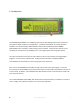
1 Introduction Figure 1: GLT24064 Display The GLK24064-25/GLT24064 is an intelligent graphic liquid crystal display engineered to quickly and easily add an elegant creativity to any application. In addition to the RS232, TTL and I2C protocols available in the standard model, USB and RS422 communication models allow the GLK2406425/GLT24064 to be connected to a wide variety of host controllers. Communication speeds of up to 115.
2 Quick Connect Guide 2.
2.2 Standard Module The standard version of the GLK24064-25/GLT24064 allows for user configuration of two common communication protocols. First, the unit can communicate using serial protocol at either RS323 or TTL voltage levels. Second, it can communicate using the Inter-Integrated Circuit connect, or I2C protocol. Connections for each protocol can be accessed through the six pin Extended Communication/Power Header as outlined in the Serial Connections and I2C Connections sections below.
2. Make the connections. a. Connect the six pin female header of the Extended Communication/Power Cable to the Communication/Power Header of your GLK24064-25/GLT24064. b. Insert the male end of your serial cable to the corresponding DB9 header of the Extended Communication/Power Cable and the mate the female connector with the desired communication port of your computer. c. Select an unmodified floppy cable from a PC power supply and connect it to the power header of the Communication/Power Cable. 3.
2.3 USB Module The GLK24064-25-USB/GLT24064-USB offers a single USB protocol for easy connection to a host computer. The simple and widely available protocol can be accessed using the on board mini B style USB connector as outlined in the USB Connections section. Recommended Parts The External Mini USB cable is recommended for the GLK24064-25USB/GLT24064-USB display. It will connect to the miniB style header on the unit and provide a connection to a regular A style USB connector, commonly found on a PC.
2.4 RS422 Module The GLK24064-25-422/GLT24064-422 provides an industrial alternative to the standard RS232 communication protocol. Rather than single receive and transmit lines, the RS422 model uses a differential pair for the receive and transmit signals to reduce degradation and increase transmission lengths. Power can be transmitted at distance to a -VPT module or supplied from the immediate vicinity to a regular or -V unit.
3 Software The multiple communication protocols available and simple command structure of the GLK2406425/GLT24064 means that a variety of applications can be used to communicate with the display. Text is sent to the display as a character string, for example, sending the decimal value 41 will result in an 'A' appearing on the screen. A single control character is also available. Commands are merely values prefixed with a special command byte, 254 in decimal.
Figure 6: MOGD# Command Example Again, the clear screen command is sent to a connected display, this time using the MOGD# Send Numeric function command style. Scripts can be run as a whole using the Play button from the toolbar or as single commands by selecting Step; once executed it must be Reset. Before issuing commands, it is a good idea to ensure communication with a display is successful using the autodetect button.
4 Hardware 4.1 Standard Model Extended Communication/Power Header Table 4: Extended Communication/Power Pinout Figure 7: Extended Communication/Power Header Pin 1 2 3 4 5 6 Function Vcc Rx (SCL) Tx (SDA) Gnd CTS RTS The Extended Communication/Power Header provides a standard connector for interfacing to the GLK24064-25/GLT24064. Voltage is applied through pins one and four of the four pin Communication/Power Header.
Power Through DB9 Jumper In order to provide power through pin 9 of the DB-9 Connector you must connect the Power Through DB-9 Jumper labelled R42, as illustrated below. This connection can be made using a zero ohm resistor, recommended size 0603, or a solder bridge. The GLK24064-25/GLT24064 allows all voltage models to use the power through DB-9 option, see the Voltage Specifications for power requirements.
4.2 USB Model Mini USB Connector Table 6: Mini USB Pinout Pin 1 2 3 5 Figure 10: Mini USB Connector Function Vcc DD+ Gnd The GLK24064-25-USB/GLT24064-USB comes with a familiar Mini USB Connector to fulfill both communication and power needs*. The standard MiniB style header can be connected to any other USB style using the appropriate cable. Most commonly used with a PC, this connection creates a virtual com port that offers a simple power solution with a familiar communication scheme.
4.3 RS422 Model RS422 Header Table 8: RS422 Pinout Pin 1 2 3 4 5 6 Function Gnd Rx (Y) Inv Rx (Z) Inv Tx (B) Tx (A) Vcc Figure 12: RS422 Header The six pin RS422 interface header of the GLK24064-25-422/GLT24064-422 offers power and ground connections as well as two differential pair communication lines. Regular and inverted lines are provided for both receive and transmit signals. Power is supplied locally to the regular or –V variants while the –VPT can receive power over a distance.
4.4 GLK Model Keypad Header Table 10: Keypad Pinout Pin 1 2 3 4 5 6 Figure 14: Keypad Header Function Gnd Row 1 Row 2 Row 3 Row 4 Row 5 Pin 7 8 9 10 11 12 Function Column 1 Column 2 Column 3 Column 4 Column 5 Gnd/Vcc* To facilitate user input, the GLK24064-25 provides a Keypad Interface Connector which allows a matrix style keypad of up to twenty-five keys to be directly connected to the display module. Key presses are generated when a short is detected between a row and a column.
4.5 GLT Model Touch Screen The GLT24064 facilitates user touch input in one of two distinct ways. Coordinate mode will report events by supplying their exact position on the screen. Region mode will report events within defined boundaries on the screen. Both modes are outlined below. Coordinate Mode In coordinate mode all touch events are reported using three single byte values. First, the type of event is transmitted, followed by the x and y coordinates of its position.
4.6 Common Features General Purpose Outputs Table 13: GPO Pinout Figure 15: GPO Header Pin 1 2 3 4 5 6 7 Function GPO 1 GPO 2 GPO 3 GPO 4 GPO 5 GPO 6 Vcc Pin 8 9 10 11 12 13 14 Function Gnd Gnd Gnd Gnd Gnd Gnd Gnd A unique feature of the GLK24064-25/GLT24064 is the ability to control relays* and other external devices using either one or six General Purpose Outputs. Each can source up to 10mA of current at five volts when on or sink 20mA at zero volts when off.
5 Troubleshooting 5.1 Power In order for your Matrix Orbital display to function correctly, it must be supplied with the appropriate power. If the power LED near the top right corner of the board is not illuminated, power is not applied correctly. Try following the tips below. First, check the power cable which you are using for continuity. If you don't have an ohm meter, try using a different power cable, if this does not help try using a different power supply.
5.3 Communication When communication of either text or commands is interrupted, try the steps below. • • • • • • • • First, check the communication cable for continuity. If you don't have an ohm meter, try using a different communication cable. If you are using a PC try using a different Com/USB Port. Next, please ensure that the display module is set to communicate on the protocol that you are using, by checking the Protocol Select Jumpers.
6 Commands 6.1 Communication 1.1 Change Baud Rate Dec 254 57 Speed Hex FE 39 Speed ASCII ■ 9 Speed Immediately changes the baud rate. Not available in I2C. Baud rate can be temporarily forced to 19200 by a manual override. Speed Byte Valid settings shown below. v8.0 Table 16: Accepted Baud Rate Values Rate Speed 9600 207 14400 138 19200 103 28800 68 38400 51 57600 34 76800 25 115200 16 1.2 Change I2C Slave Address Dec 254 51 Address v8.
1.6 Turn Dec 254 58 Almost Full Almost Empty v8.0 Software Flow Hex FE 3A Almost Full Almost Empty Control On ASCII ■ : Almost Full Almost Empty Enables simple flow control. The display will return a single, Xoff, byte to the host when the display buffer is almost full and a different, Xon, byte when the buffer is almost empty. Full value should provide enough room for the largest data packet to be received without buffer overflow.
6.2 Text 2.1 Clear Screen Dec 254 88 Hex FE 58 ASCII ■X Clears the contents of the screen. v8.0 2.2 Go Home Dec 254 72 Hex FE 48 ASCII ■H Returns the cursor to the top left of the screen. v8.0 2.3 Set Cursor Position Dec 254 71 Column Row Hex FE 47 Column Row ASCII ■ G Column Row Sets the cursor to a specific cursor position where the next transmitted character is printed. Column Byte Value between 1 and number of character columns. Row Byte Value between 1 and number of character rows. v8.0 2.
2.6 Set Text Window Dec 254 42 ID v8.3 Hex FE 2A ID ASCII ■ * ID Sets the text window to which subsequent text and commands will apply. Default (entire screen) is window 0. ID Byte Unique text window to use. 2.7 Clear Text Window Dec 254 44 ID Hex FE 2C ID ASCII ■ , ID Clear the contents of a specific text window, similar to the clear screen command. ID Byte Unique text window to clear. v8.3 2.8 Initialize Label Dec 254 45 ID X1 Y1 X2 Y2 Vert Hor Font Background CharSpace v8.
6.3 Drawing 3.1 Set Drawing Colour Dec 254 99 Colour Hex FE 63 Colour ASCII ■ c Colour Set the colour to be used for all future drawing commands that do not implicitly specify colour. Colour Byte 0 for background or any other value for text colour. v8.0 3.2 Draw Pixel v8.0 Dec 254 112 X Y Hex FE 70 X Y ASCII ■p X Y Draw a single pixel at the specified coordinate using the current drawing colour. X Byte Horizontal position of pixel to be drawn. Y Byte Vertical position of pixel to be drawn. 3.
3.6 Draw a Filled Rectangle Dec 254 120 Colour X1 Y1 X2 Y2 Hex FE 78 Colour X1 Y1 X2 Y2 ASCII ■ x Colour X1 Y1 X2 Y2 Draw a filled rectangle using the colour specified; current drawing colour is ignored. Colour Byte 0 for background or any other value for text colour. X1 Byte Leftmost coordinate. Y1 Byte Topmost coordinate. X2 Byte Rightmost coordinate. Y2 Byte Bottommost coordinate. v8.0 3.
3.10 Draw a Filled Circle Dec 254 124 X Y Radius Hex FE 7C X Y Radius ASCII ■ | X Y Radius Draw a filled circle using the current drawing colour. X Byte Horizontal coordinate of the circle centre. Y Byte Vertical coordinate of the circle centre. Radius Byte Distance between the circle perimeter and centre. v8.3 3.11 Draw an Ellipse Dec 254 125 X Y XRadius YRadius Hex FE 7D X Y XRadius YRadius ASCII ■ } X Y XRadius YRadius Draw an elliptical frame one pixel wide using the current drawing colour.
3.14 Initialize a Bar Graph Dec 254 103 ID Type X1 Y1 X2 Y2 v8.3 Hex FE 67 ID Type X1 Y1 X2 Y2 ASCII ■ g ID Type X1 Y1 X2 Y2 Initialize a bar graph in memory for later implementation. Graphs can be located anywhere on the screen, but overlapping may cause distortion. Graph should be filled using the Draw a Bar Graph command. ID Byte Unique bar identification number, between 0 and 255. Type Byte Graph style, see Bar Graph Types. X1 Byte Leftmost coordinate. Y1 Byte Topmost coordinate.
3.17 Initialize a Strip Chart Dec 254 110 ID X1 Y1 X2 Y2 Min Max Step Style ID v8.3 Hex FE 6E ID X1 Y1 X2 Y2 Min Max Step Style ID ASCII ■ n ID X1 Y1 X2 Y2 Min Max Step Style ID Designate a portion of the screen for horizontal scrolling. Can be used to create scrolling graphs or marquee text. ID Byte Unique chart identification number, value between 0 and 7. X1 Byte Leftmost coordinate of the strip chart, zero indexed from left. Y1 Byte Topmost coordinate of the strip chart, zero indexed from top.
6.4 Fonts 4.1 Upload a Font File Dec 254 36 ID Size Data Hex FE 24 ID Size Data ASCII ■ $ ID Size Data Upload a font to a graphic display. To create a font see the v8.0 Font File Creation section, for upload protocol see the File Transfer Protocol or XModem Upload Protocol entries. Default font is ID 1. ID* Short Unique font identification number, value between 0 and 1023. Size* Integer Size of the entire font file. Data Byte(s) Font file data, see the Font File Creation example.
Font File Creation Matrix Orbital graphic displays are capable of displaying text in a wide variety of styles customizable to suit any project design. Front files alter the style of text and appearance of the display. By default, a Matrix Orbital graphic display is loaded with a small filled font in slot one and a future bk bt 16 style in slot two. Both are available at www.matrixorbital.ca/software/graphic_fonts.
The character data is a binary graphical representation of each glyph in a font. Each character is drawn on a grid containing as many rows as the height specified in the header and as many columns as the width specified in the character table. Cells are drawn by writing a one in their location and cleared by setting a value of zero. Starting at the top left, moving right, then down, eight of these cells form a character data byte.
6.5 Bitmaps 5.1 Upload a Bitmap File Dec 254 94 ID Size Data Hex FE 5E ID Size Data ASCII ■ ^ ID Size Data Upload a bitmap to a graphic display. To create a bitmap see the Bitmap File Creation section, for upload protocol see the File Transfer Protocol or XModem Upload Protocol entries. Start screen is ID 1. ID* Short Unique bitmap identification number, value between 0 and 1023. Size* Integer Size of the entire bitmap file. Data Byte(s) Bitmap file data, see the Bitmap File Creation example.
5.5 Draw a Bitmap Directly Dec 254 100 X1 Y1 Data v8.0 Hex FE 64 X1 Y1 Data ASCII ■ d X1 Y1 Data Draw a bitmap directly to the graphic display without saving to memory. Cannot be implemented in a script. X1 Byte Leftmost coordinate of bitmap. Y1 Byte Topmost coordinate of bitmap. Data Byte(s) Bitmap file data, see the Bitmap File Creation example.
Bitmap Masking Like a regular bitmap, a mask can be loaded to the display and used to create a more polished result when drawing in populated areas. When defining a mask, all active values will clear any background information, while any inactive values will leave it untouched. This is best described with an example.
6.6 9-Slices 6.1 Upload a 9-Slice File Dec 254 92 3 ID Size Data Hex FE 5C 03 ID Size Data ASCII ■ \ ETX ID Size Data Upload a 9-slice file to a graphic display. To create a 9-slice see the 9-Slice File Creation section, for upload protocol see the File Transfer Protocol or XModem Upload Protocol entries. ID Short Unique 9-slice identification number, value between 0 and 1023. Size Integer Size of the 9-slice file. Data Byte(s) 9-slice file data, see the 9-Slice File Creation example. v8.3 6.
9-Slice File Creation A 9-slice file is a scalable graphic composed of nine different bitmap sections as shown below. Figure 19: Adobe 9-slice Representation The 9-slice file format requires that the bitmap dimensions and the locations of divisions be defined before a graphic is uploaded normally as shown in the Bitmap File Creation example. Table 30: 9-slice file format Width Height Top Bottom Left Right Bitmap Data 34 One byte representing the width of the entire bitmap.
6.7 Animations 7.1 Upload an Animation File Dec 254 92 4 File ID Size Data v8.3 Hex FE 5C 04 File ID Size Data ASCII ■ \ EOT File ID Size Data Upload an animation file to a graphic display. To create an animation see the Animation File Creation section, for upload protocol see the File Transfer Protocol or XModem Upload Protocol entries. Up to 16 animations can be displayed on the screen at one time, using the Display Animation command, but up to 1024 can be stored in memory for later use.
7.6 Get Dec 254 196 ID Animation Hex FE C4 ID Frame ASCII ■ ─ ID Get the current frame of a displayed animation. ID Byte Animation number to request frame number, value between 0 and 15. Response Byte Current frame number of the animation specified, value between 0 and 31. v8.3 Animation File Creation An animation file is a series of bitmaps, each displayed for a specified length of time within a continuous rotation.
6.8 General Purpose Output 8.1 General Purpose Output On Dec 254 87 Number Hex FE 57 Number ASCII ■ W Number Turns the specified GPO on, sourcing current from an output of five volts. Number Byte GPO to be turned on. v8.0 8.2 General Purpose Output Off v8.0 Dec 254 86 Number Hex FE 56 Number ASCII ■ V Number Turns the specified GPO off, sinking current to an output of zero volts. Number Byte GPO to be turned off. 8.3 Set Start Up GPO State Dec 254 195 Number State v8.
6.9 Dallas One-Wire 9.1 Search for a One-Wire Device Dec 254 200 2 v8.0 Hex FE C8 02 ■ ╚ SOT ASCII Sends a search query to each of the up to 32 devices on the one wire bus. Any connected device will respond with an identification packet. Response Bytes [14] Dallas One-Wire identification packet as shown below.
6.10 Piezo Buzzer 10.1 Activate Piezo Buzzer Dec 254 187 Frequency Time v8.0 Hex FE BB Frequency Time ■ ╗ Frequency Time ASCII Activates a buzz of specific frequency from the onboard piezo buzzer for a specified length of time. Frequency Short Frequency of buzz in hertz. Time Short *Duration of the beep in milliseconds. *Note: When a beep precedes a delay command, the duration of the beep must be shorter than that of the delay. 10.
6.11 Keypad 11.1 Auto Dec 254 65 v8.0 Transmit Key Hex FE 41 Presses On ASCII ■A Key presses are automatically sent to the host when received by the display. Use this mode for I2C transactions. 11.2 Auto Dec 254 79 v8.0 Transmit Key Hex FE 4F Presses Off ASCII ■O Key presses are held in the 10 key buffer to be polled by the host using the Poll Key Press command. Default is Auto Transmit on. 11.3 Poll Key Press Dec 254 38 v8.
11.7 Auto Dec 254 96 Repeat Mode Hex FE 60 Off ASCII ■` Turns auto repeat mode off. Default is on (typematic). v8.0 11.8 Assign Keypad Codes Dec 254 213 Key Down Key Up v8.0 Hex FE D5 Key Down Key Up ■ ╒ Key Down Key Up ASCII Assigns the key down and key up values sent to the host when a key press is detected. A key up and key down value must be sent for every key, a value of 255 will leave the key unaltered. Defaults are shown below. Key Down Bytes [25] Key down values. Key Up Bytes [25] Key up values.
6.12 Touchpad 12.1 Set Touch Mode Dec 254 135 Mode v8.0 Hex FE 87 Mode ■ ç Mode ASCII Sets the method used to return touch events. Region mode will return a single value for events in defined areas. Coordinate mode will return event, x position, and y position bytes for each press, drag, or release. Mode Byte Touch reporting mode, 0 for region or 1 for coordinate mode. Default is coordinate. 12.2 Set Region Reporting Mode Dec 254 136 Mode v8.
12.6 Create a Slider Dec 254 186 ID Type X Y Width Height Control Width Min Max v8.3 Hex FE BA ID Type X Y Width Height Control Width Min Max ■ ║ ID Type X Y Width Height Control Width Min Max ASCII Draw a slider on the screen that responds visually and numerically when tapped or slid. Slider regions respond with a value of 83, their ID, then two byte length current X and Y coordinates when activated. ID Byte Unique slider identification number, maximum 32 regions/sliders.
12.10 Set Dec 254 138 Threshold Pressure Hex FE 8A Threshold ■ è Threshold Threshold ASCII Sets the pressure required to trigger a touch event. Threshold Short Pressure threshold value. Default is 1000. v8.0 12.11 Run Dec 254 139 v8.0 Touchpad Hex FE 8B Calibration ASCII ■ï Triggers an interactive calibration of the touchpad. User will be required to touch various points on the screen during calibration.
6.13 Display Functions 13.1 Backlight On Dec 254 66 Minutes v8.0 Hex FE 42 Minutes ASCII ■ B Minutes Turns the display backlight on for a specified length of time. If an inverse display color is used this command will essentially turn on the text. Minutes Byte Number of minutes to leave backlight on, a value of 0 leaves the display on indefinitely. 13.2 Backlight Off Dec 254 70 Hex FE 46 ASCII ■F Turns the display backlight off. If an inverse display colour is used this command will turn off the text.
6.14 Scripting 14.1 Upload a Script File Dec 254 92 2 ID Length Data v8.3 Hex FE 5C 02 ID Length Data ASCII ■ \ STX ID Length Data Save a list of commands to be executed at a later time. Bytes are saved as if they are being sent by the host, for upload protocol see the File Transfer Protocol or XModem Upload Protocol entries. ID Short Unique identification number of the script, value between 0 and 1023. Length Integer Length of the script in bytes.
6.15 Filesystem 15.1 Delete Filesystem Dec 254 33 89 33 v8.0 Hex FE 21 59 21 ASCII ■!Y! Completely erase all fonts and bitmaps from a graphic display. Extended length of the command is intended to prevent accidental execution. To ensure filesystem integrity, cycle power to the display after erasure. 15.2 Delete a File Dec 254 173 Type ID v8.0 Hex FE AD Type ID ASCII ■ ¡ Type ID Removes a single font or bitmap file given the type and unique identification number. Cycle power after deletion.
15.6 Filesystem Download Dec 254 48 Hex FE 30 ASCII ■0 Downloads complete filesystem containing all fonts and bitmaps stored in the display using the File Transfer Protocol. A veritable heap of data. Response Integer Size of the filesystem to download. Byte(s) Filesystem data to download. v8.0 15.7 File Download Dec 254 178 Type ID v8.0 Hex FE B2 Type ID ■ ▓ Type ID ASCII Downloads a single font or bitmap file from the display to the host using the File Transfer Protocol.
15.10 XModem Dec 254 222 133 6 48 v8.3 Filesystem Hex FE DE 85 6 30 Download ASCII ■ ▐ à ACK 0 Downloads the complete filesystem using the XModem Upload Protocol. A veritable heap of data, transmitted at a decent pace. Response Integer Size of the filesystem to download. Byte(s) Filesystem data to download, an even multiple of 256 bytes. 15.11 XModem File Upload Dec 254 220 133 6 48 File ID Type Size Data v8.
Once a file is confirmed to fit within the display, the upload will begin. A protocol is used here to ensure each byte is uploaded successfully. After each byte is sent, the module will echo it back to the host. It should then be checked against the value originally sent before a confirmation byte of 1 is returned. If the transmitted and echoed values do not match the upload should be aborted by sending a value of 8 instead.
send a 128 byte block of data followed by that blocks high and low CRC16 bytes. The display then performs a CRC check on the data receive and ACKs if it matches that which was sent. Transfer continues with a block count and continues in this way until the end of file is reached. Files may be padded with 255 values to reach an even multiple of 128 bytes in size, but the download command will always report true size.
6.16 Data Security 16.1 Set Remember Dec 254 147 Switch v8.0 Hex FE 93 Switch ASCII ■ ô Switch Allows changes to specific settings to be saved to the display memory. Writing to non-volatile memory can be slow and each change consumes 1 write of at least 100,000 available. The Command Summary outlines which commands are saved always, never, and when this command is on only. Remember is off by default. Switch Byte 1 for on or 0 for off. 16.2 Set Data Lock Dec 254 202 245 160 Level v8.
6.17 Miscellaneous 17.1 Write Customer Data Dec 254 52 Data v8.0 Hex FE 34 Data ASCII ■ 4 Data Saves a user defined block of data to non-volatile memory. Useful for storing display information for later use. Data Byte [16] User defined data. 17.2 Read Customer Data Dec 254 53 v8.0 Hex FE 35 ASCII ■5 Reads data previously written to non-volatile memory. Data is only changed when written, surviving power cycles. Response Byte [16] Previously saved user defined data. 17.
17.6 Read Module Type Dec 254 55 Hex FE 37 ASCII ■7 Causes display to respond with its module number. Response Byte Module number, see Sample Module Type Responses for a partial list. v8.0 Table 50: Sample Module Type Responses 105 106 110 GLT24064 GLT24064-USB GLT24064-422 21 107 109 GLK24064-25 GLK24064-25-USB GLK24064-25-422 17.7 Read Screen Dec 254 184 Hex FE B8 ■╕ ASCII Return a two byte screen size, followed by the current commanded state of each pixel on the screen.
7 Appendix 7.1 Command Summary Available commands below include identifying number, required parameters, the returned response and an indication of whether settings are remembered always, never, or with remember set to on.
Table 53: Drawing Command Summary Name Set Drawing Colour Draw Pixel Draw a Line Continue a Line Draw a Rectangle Draw a Filled Rectangle Draw a Rounded Rectangle Draw a Filled Rounded Rectangle Draw a Circle Draw a Filled Circle Draw an Ellipse Draw a Filled Ellipse Scroll Screen Initialize a Bar Graph Initialize 9-Slice Bar Graph Draw a Bar Graph Dec 99 112 108 101 114 120 128 129 123 124 125 127 89 103 115 105 Hex 63 70 6C 65 72 78 80 81 7B 7C 7D 7F 59 67 73 69 ASCII c p l e r x Ç ü { | } Initialize
Table 56: 9-Slice Command Summary Name Dec Hex ASCII Parameters Upload a 9-Slice File 92 3 5C 03 \ ETX Short, Integer, Byte[] Upload a 9-Slice Mask 92 6 5C 06 \ ACK Short, Integer, Byte[] Display a 9-Slice 91 5B [ Short, Byte[4] Response See 9-Slice File Creation See 9-Slice File Creation None Remembered Always Always Never Table 57: Animation Command Summary Name Dec Hex ASCII Parameters Upload an Animation File 92 4 5C 04 \ EOT Short, Integer, Byte[] Display Animation Del
Table 61: Keypad Command Summary Name Auto Transmit Key Presses On Auto Transmit Key Presses Off Poll Key Press Clear Key Buffer Set Debounce Time Auto Repeat Mode Off Assign Keypad Codes Set Typematic Delay Set Typematic Interval Dec 65 79 38 69 85 96 213 159 158 Hex 41 4F 26 45 55 60 D5 9F 9E ASCII A ` & E U ` ╒ ƒ ₧ Parameters None None None None Byte None Byte[25], Byte[25] Byte Byte Response None None Byte None None None None None None Remembered Remember On Remember On Never Never Remember On Re
Table 65: Filesystem Command Summary Name Delete Filesystem Delete a File Get Filesystem Space Get Filesystem Directory Filesystem Upload Filesystem Download File Download Dec 33, 89, 33 173 175 179 176 48 178 Hex 21, 59, 21 AD AF B3 B0 30 B2 ASCII !, Y, ! ¡ » │ ░ 0 ▓ File Move 180 B4 ┤ XModem Filesystem Upload XModem Filesystem Download 219, 133, 6, 48 222, 133, 6, 48 220, 133, 6, 48 221, 133, 6, 48 DB, 85, 6, 30 DE, 85, 6, 30 DC, 85, 6, 30 DD, 85, 6, 30 █, à, ACK, 0 ▐, à, ACK, 0 ▄, à, ACK, 0 ▌
7.2 Block Diagram Figure 20: Functional Diagram 7.3 Environmental Specifications Table 68: Environmental Limits Operating Temperature Storage Temperature Operating Relative Humidity Standard *Extended (-E) 0°C to +50°C -20°C to +70°C -10°C to +60°C -30°C to +80°C Maximum 90% non-condensing *Note: The Extended Temperature option is not available for any variant of the GLT24064. 7.
7.
Figure 23: USB Model Dimensional Drawing 62 Figure 24: RS422 Model Dimensional Drawing Command Summary
7.1 Optical Characteristics Table 72: Display Optics Module Size 180.00 x 65.00 x 30.5 mm Viewing Area 132.2 x 39.2 mm Active Area 127.16 x 33.88 mm Pixel Size 0.49 x 0.49 mm Pixel Pitch 0.53 x 0.53 mm Viewing Direction 12 O’clock Viewing Angle -30 to +30 ° Contrast Ratio 3 Backlight Half-Life (YG) 50,000 Hours Backlight Half-Life (WB & GW) 20,000 Hours *Note: Backlight half-life is rated for normal operating conditions only: 25±10°C and 45±20% Relative Humidity. 8 Ordering 8.
8.3 Accessories Power Table 75: Power Accessories PCS Standard Power Cable Communication Table 76: Communication Accessories 64 CSS1FT 1 ft. Serial Cable CSS4FT 4 ft.
Peripherals Table 77: Peripheral Accessories KPP4x4 16 Button Keypad Command Summary 65
9 Definitions ASCII: American standard code for information interchange used to give standardized numeric codes to alphanumeric characters. BPS: Bits per second, a measure of transmission speed. Byte: An unsigned data packet that is eight bits long. DOW: Dallas One-Wire protocol, similar to I2C, provides reduced data rates at a greater distance. One wire carries data, while two others supply power and ground.