GTT70A Hardware Manual Revision 1.3 PCB Revision: 2.0 or Higher Firmware Revision: 2.
Revision History Revision 1.3 1.2 1.1 1.
Contents 1 Introduction ............................................................................................................................................... 1 2 Features ..................................................................................................................................................... 2 3 Ordering ..................................................................................................................................................... 3 3.
5.3 Communication ................................................................................................................................. 11 5.4 Factory Defaults ................................................................................................................................ 11 6 Appendix .................................................................................................................................................. 12 6.1 Dimensional Drawing .......................
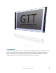
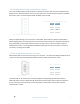
Figure 1: The GTT70A Display 1 Introduction The Matrix Orbital GTT70A is a full colour TFT display with an integrated touch screen, crafted to become a crisp, controllable canvas for creativity. Utilizing an extended version of our widely used command library and industry standard communication protocols, the customizable GTT70A series contains an intelligent display that will quickly become the gorgeous face of your application.
2 Features In addition to a beautiful full-colour TFT screen, seamless incorporation of a touch panel provides sleek user input while a small piezo speaker and vibratory motor can offer audio and tactile feedback for a completely interactive experience. Storage of fonts and bitmaps within the swappable onboard SD memory card allows for a co-ordinated appearance in any design.
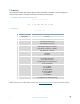
3 Ordering The innovative GTT70A, with all of the features mentioned above, is available in various voltage and communication options to provide a sleek touch of creativity to any project. 3.1 Ordering Part Numbering Scheme Table 1: Part Numbering Scheme GTT 70 A -TPR -BLS -B1 -H1 -CU -V5 1 2 3 4 5 6 7 8 9 3.
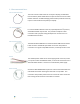
3.3 Recommended Parts Serial Communication The most common cable choice for the any GTT display, the Extended Communication/ Power Cable offers a simple connection to the unit with familiar interfaces. A DB9 and floppy power header provide all necessary input to communicate to and power your display. Figure 3: ESCCPC5V I2C Communication For a more flexible interface to the GTT, especially with the I2C protocol, a Breadboard Cable may be used.
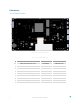
4 Hardware 4.
4.2 Extended Serial Communication/Power Header The communication/power header provides an interface for the two most common GTT70A protocols: RS232 and TTL. With the ability to connect to a PC serial port or microcontroller and optional hardware flow control, this is the most versatile header available on the GTT70A.
Alternate USB Communication Header Some advanced applications may prefer the straight four pin connection offered through the optional Alternate USB Header. The Alternate USB Header may be added to the USB model for an added charge as part of a custom order. Please use the Contact section to reach Sales for additional details. Drivers The latest drivers are available for download in a zipped file format at www.matrixorbital.ca/drivers.
4.2 Alternate Power Connector The Alternate Power Connector provides the ability to power the GTT70A using a second cable. This connection is required for USB protocol due to the power requirements of the GTT70A.
4.4 Mass Storage Mini-B USB Header The GTT70A comes with a secondary Mini-B USB connector to access the SD memory card as a mass storage device for easier access to the files contained on the card. Table 10: Mass Storage USB Pinout Pin 1 2 3 5 Function Vcc DD+ Gnd Figure 15: Mass Storage USB Connector The mass storage selector must be placed on the pins labelled “A” to use this function, please refer to the Mass Storage Mode section for further information.
4.5 General Purpose Outputs A unique feature of the GTT70A is the ability to control relays* and other external devices using either one of six General Purpose Outputs. Table 11: GPO Pinout Pin 1 2 3 4 5 6 7 8 Function Gnd GPO 1 GPO 2 GPO 3 GPO 4 GPO 5 GPO 6 Vcc Pin 8 9 10 11 12 13 14 16 Function Gnd Gnd Gnd Gnd Gnd Gnd Gnd Gnd Figure 16: GPO Header Each can source up to 15mA of current at five volts when on, or sink 15mA at zero volts when off.
5 Troubleshooting 5.1 Power To function correctly, the GTT70A must be supplied with the appropriate power. If the power LED near the top right corner of the board is not illuminated, power is not applied correctly. Try the tips below. GTT devices have specific power requirements. Ensure the correct voltage and sufficient current are available to your device by consulting the Power Consumption table. Check the power cable which you are using for continuity.
6 Appendix 6.
6.2 Power Consumption 6.3 Environmental Table 13: Required Supply Voltage Parameter Min Typ Max Unit Supply Voltage 4.75 5.0 5.25 V 9.0 12.0 35.
Communication Characteristics Table 20: RS232 Interface Characteristics Parameter Table 21: USB Interface Characteristics Parameter Min Typ Max Unit Input Threshold Low Input Threshold High Output Voltage Swing 0.6 1.2 - V - 1.5 2.4 V - V 7 kΩ - Ω ±5.0 ±5.4 Input Resistance 3 Output Resistance 5 300 10M Output Short Circuit Current - Min Typ Max Unit Static Output High 2.8 - 3.6 V Static Output Low - - 0.3 V Input Differential Threshold 0.
7 Definitions 9-Slice: Graphic format used to scale bitmaps, usually rectangular, without distorting their geometry. Nine regions define the object center, four corners, and four sides for accurate up or down scaling. ASCII: American standard code for information interchange used to give standardized numeric codes to alphanumeric characters. BPS: Bits per second, a measure of transmission speed. GUI: Graphical user interface.