www.szmatrix.com PEL-8000 Series Electronic Load User Manual MATRIX TECHNOLOGY INC. Version number: V2.
Contents CHAPTER I INTRODUCTION....................................................................................................................................1 CHAPTER II TECHNICAL SPECIFICATIONS............................................................................................................. 2 2.1 THE MAIN TECHNICAL SPECIFICATIONS................................................................................................................. 2 3.1 POST.......................................
4.3 INPUT CONTROL............................................................................................................................................... 21 4.3.1 Short circuit operation (SHORT)..........................................................................................................21 4.3.2 Input switch operation......................................................................................................................... 21 4.4 ELECTRONIC LOAD OPERATING RANGE..............
Chapter One Introduction The PEL-8000 series is a new generation of DC electronic load. It adopts high performance chip, high speed and high precision design. It can provide the resolution of 0.1mV and 0.01mA (the basic accuracy is 0.05% and the basic current rising speed is 2.5A /us) Novel, rigorous scientific production process, compared to similar products, more cost-effective.
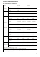
Chapter II Technical Specifications 2.1 The main technical specifications Model Input Rating CC mode CV mode CR mode CW mode V Measureme nt PEL-8150 PEL-8300 Power 150W 300W Current 0-30A 0-60A Voltage 0-150V Range 0-3A 0-30A 0-6A 0-60A Resolution 0.1mA 1mA 0.1mA 1mA Accuracy 0.03%-0.05%FS Range 0.1-19.999V 0.1-150V 0.1-19.999V 0.1-150V Resolution 1mV 10mV 1mV 10mV Accuracy 0.03%+0.02%FS Range 0.03Ω-10kΩ 0.03Ω-5kΩ 0.03Ω-10kΩ 0.
Current soft start time: 1mS;2mS;5mS;10mS;20mS;50mS;100mS;200mS;500mS;1000mS; Accuracy: ± 15%, offset+10%FS Current(CC) ≈3A Valtge(CV) 0V Resistance(CR) ≈55mΩ Operating 0-40℃ Storage (-10℃~70℃) Dimension W*H*D(mm) 214*108*365 Weight Kg 3.5 Short Circuti Temperature ≈33A ≈6.6A ≈66A ≈25mΩ 3.
Chapter III Quick Start 3.1 POST First of all, the user needs to connect the power cord correctly and power on. The following are the specific steps of self-test. step VFD display details When the electronic load SYSTEM SELF TEST Vx.x power is turned on version number EPROM ERROR After about 1S System self-test, and display the product model and software If the EEPROM is damaged or there is a loss of the last load in the EEPROM, the VFD displays a message (about 2S) ERROR CAL.
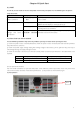
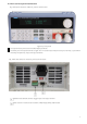
3.3 front and rear panel introduction PEL-8000 series electronic load front panel as shown below Figure 3.2 Front panel 1 The top half of the panel is the black VFD display and knob 2 The lower part of the panel from left to right are 0-9 numeric keys and ESC exit key, function key, up and down move key and Enter key, input and output terminals.
3.
COMM.
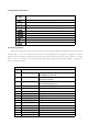
TEST CURRENT Test current TEST VOLTAGE Test voltage TEST POWER Test the power TEST RESI Test resistance DELAY TIME Test delay time (0.2 ~ 25.
Chapter IV Panel Operation 4.1 Basic operation mode Electronic load can work in the following four modes: 1. Constant current mode of operation (CC). 2. Constant voltage operation mode (CV). 3. Constant resistance operation mode (CR). 4. Constant power operation mode (CW) 4.1.1 Constant current mode of operation (CC) In constant current mode, the electronic load consumes a constant current, regardless of the input voltage, as shown in the following figure.
automatically adjusted to the open state. If the ONSET load voltage is greater than the OFFSET unload voltage, the load may avoid frequent unloading of the load near the critical point of the unloading voltage, which may better protect the source under test. Figure 4.
mode. In this case, if the input status is OFF, the upper right corner of the display panel will display "OFF". To change the input status to ON, press the On / Off button. The "CC_S" or "Unreg" "CC_S" indicates that the expected constant current value is reached. If "Unreg" indicates that the load can not be adjusted to the preset current value correctly, check whether the source to be measured is correctly connected and turned on or whether the source under test can output the preset current value.
Figure 4.5 Constant resistance mode 4.1.2.1 Standard fixed resistance mode Press the CR button, the load shows "STANDARD RESI = xxxxxxxxΩ", prompts the current set resistance, then press the numeric keys and decimal point keys on the panel, enter the desired constant resistance value from high to low, and press the Enter key to confirm , Load into the standard resistance mode. In this case, if the input status is OFF, the upper right corner of the display panel will display "OFF".
4.1.2.3 fixed resistance switch voltage mode Figure 4.6 Constant resistance conversion constant voltage mode Constant resistance to switch voltage mode, you can better protect the test source is not over-discharge damage.
status bit, press the On / Off button. The upper right corner of the display panel displays "CV" or "Unreg" "Indicates that the voltage reaches the expected value," Unreg "means that the load can not be correctly adjusted to the preset voltage, please check the source is connected correctly and turned on, or the source voltage is too low to be measured, or the output current capacity exceeds the load Maximum load current.
If the input status is OFF, the upper right corner of the display panel will display "OFF". To change the input status bit to ON, press the On / Off button.
key to confirm, the load display "OFFSET VOLT = xxxxxxxxV" prompts the current unloading voltage, at this time you can press the number keys and decimal point keys on the panel, from high to low order Enter the required unloading voltage value, and press Enter key to confirm, the load into the loading and unloading constant power mode. If the input status is OFF, "OFF" is displayed in the upper right corner of the display panel. To change the input status to ON, press the On / Off button.
for each trigger received. Figure 4.12 Trigger mode of operation 4.2.4 Dynamic test parameter settings Press the Shift + 6 (S_Tran) button, the load displays "LEVEL A CURR = xxxxxxxxA", prompts the current set A current value, then press the numeric keys and decimal point key on the panel, enter the desired Value and press Enter to confirm. At this moment, the load displays "WIDTH A TM = xxxxxxxxmS" to indicate the current setting A duration.
4.2.5.3 Trapezoidal wave If the required four time parameters are set greater than 0, the test mode is continuous output In normal mode, the load output is trapezoidal wave. The frequency characteristics of its description with the triangular wave. 4.2.6 Trigger control When dynamic test mode is set to pulse mode or trigger mode, trigger control is activated.
4.2.7.2 Perform LIST function Press Shift + 0 to enter menu setting, press ▲ or ▼ key until the load prompts "MENU LIST", press Enter key to enter, press ▲ or ▼ key until the load prompts "LOAD LIST", press Enter key to enter, press ▲ or ▼ Key to select the serial number to be executed and press Enter to finish.
the valid range of this delay time is 0.1 ~ 25.5S, the smaller the setting value, the shorter the time required for the test, However, under certain conditions, too small parameters may affect the test result because the power supply is not stable. Please carefully choose this parameter. The recommended data is 0.5S. Press number keys to edit and press Enter key to confirm.
After completing a test, the user can press the ▲ or ▼ key to start the single-step test mode, the load will be single-step load, each press ▲ or ▼ key, perform the previous step or the next load test, the user You can observe the actual state of each step.
Figure 4-14 Software Settings Max 4.5 protection function The load includes several protection features described below 4.5.1 Over-voltage protection (OVP) When the input voltage is greater than the maximum voltage, the load over-voltage protection, input OFF, buzzer beep, VFD display the following information "OVER VOLT".
4.5.5 Over Temperature Protection (OTP) When the load of internal power devices over 80 ℃, the load temperature protection. In this case, the input is OFF, the buzzer sounds and VFD displays the following message "OVERHEAT" 4.6 remote test function In CV, CR, CP mode, when the load consumes large current, a voltage drop will be generated on the connecting line between the instrument under test and the load terminal.
Figure 4-16 Battery capacity calculation diagram 4.8 Communication Protocol 4.8.1 Overview PEL-8000 series of electronic load, support Modbus application protocol. The data frame structure contains four parts: Additional address function code data Error checking To ensure the reliability of communication, you should ensure that the data interval of each frame should be greater than 3.5x single-byte transmission time.
3) Choose the verification method Press Shift + 0 to enter the main menu, the load will display "MENU CONFIG", press Enter to confirm, then the load will enter the config configuration menu, press up and down until the load shows "CONFIG COMM.PARITY" Enter to enter, the load display "COMM.PAR xxxxx" prompts the current calibration mode, the user can use the up and down keys to select the appropriate calibration method, and press Enter to confirm.
Request frame Byte length value Additional address 1 1~200 function code 1 0x01 initial address 2 0~0xFFFF Number of coils 2 1~16 Check code 2 Reply frame Byte length value Additional address 1 1~200 function code 1 0x01 Byte count 1 1~2 Coil status n Check code 2 Abnormal frame Byte length value Additional address 1 1~200 function code 1 0x81 Abnormal code 1 1~4 Check code 2 Example: Load communication address is 1, read load input state ISTATE Table 4.8.
Example: Load communication address is 1, control load is remote control Table 4.8.
Check code 2 Abnormal frame Byte length value Additional address 1 1~200 function code 1 0x90 Abnormal code 1 1~4 Check code 2 Example: When the load address is 1, set the constant current value IFIX to 2.3 Table 4.8.7 Table .2 to know the current value IFIX register address is 0x0A01, a 2-word floating-point number Send request: 0x01 0x10 0x0A 0x01 0x00 0x02 0x04 0x40 0x13 0x33 0x33 0xFC 0x23 Get the normal reply 0x01 0x10 0x0A 0x01 0x00 0x02 0x13 0xD0 4.8.
Table 2 registers XRAM area definition: name CMD address 0x0A00 wor Attrib d utes 1 W/R Description Command register: low 8 effective, read and write high 8 meaningless.
UBATTEND 0x0A2E 2 W/R Battery test termination voltage register, double type BATT 0x0A30 2 W/R Battery capacity register, double type SERLIST 0x0A32 1 W/R LIST serial number register, u16 type SERATEST 0x0A33 1 W/R Automatic test sequence register, u16 type IMAX 0x0A34 2 W/R Current maximum register, double type UMAX 0x0A36 2 W/R Voltage maximum register, double type PMAX 0x0A38 2 W/R Maximum power register, double type ILCAL 0x0A3A 2 W/R Calibration current low-end ta
voltage mode Battery test mode Constant voltage 38 soft-start 39 mode Change system parameters 41 Enter ON 42 Enter OFF 43 4.8.
Write register CMD 2 required Table 10 Constant Power Operation: operating register value Description Write register PFIX Double Optional Write register CMD 3 required Table 11 resistor operation: operating register value Description Write register RFIX Double Optional Write register CMD 4 required Table 12 constant current soft-start: operating register value Description Write register IFIX Double Optional Write register TMCCS Double Optional Write register CMD 20
operating register value Description Write register RFIX Double Optional Write register UCRONSET Double Optional Write register UCROFFSET Double Optional Write register CMD 33 required Table 18 constant current transfer voltage mode: operating register value Description Write register IFIX Double Optional Write register UCCCV Double Optional Write register CMD 34 required Table 19 resistor transfer voltage mode: operating register value Description Write register RFI
Safety Do not install replacement parts on the instrument yourself or perform any unauthorized modifications. Please send the instrument to the company's maintenance department for repair to ensure its safe use. Refer to the specific warnings or cautions in this manual to avoid personal injury or equipment damage. Safety signs caveat It reminds the user to pay attention to certain operational procedures, practices, conditions and other matters that may cause personal injury.