
User Manual


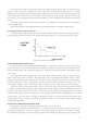


Table Of Contents
- Chapter One Introduction
- Chapter II Technical Specifications
- Chapter IV Panel Operation
- 4.1 Basic operation mode
- 4.2 dynamic test operation
- 4.3 input control
- 4.4 Electronic load operating range
- 4.5 protection function
- 4.6 remote test function
- 4.7 battery discharge test operation
- 4.8 Communication Protocol

16
key to confirm, the load display "OFFSET VOLT = xxxxxxxxV" prompts the current unloading voltage, at this time you
can press the number keys and decimal point keys on the panel, from high to low order Enter the required
unloading voltage value, and press Enter key to confirm, the load into the loading and unloading constant power
mode.
If the input status is OFF, "OFF" is displayed in the upper right corner of the display panel. To change the input
status to ON, press the On / Off button. In the upper right corner of the display panel, "CW_UN" or "Unreg" is
displayed and "CW_UN "Indicates that the expected constant power value has been reached. If" Unreg "indicates
that the load can not be adjusted to the preset power value correctly, check whether the source to be measured is
correctly connected and turned on, whether the voltage is within the normal range, or whether the source to be
measured can output the pre- Set the current absorbed by the power.
In load unload constant power mode, press Shift + 1 (V_Level) key, the load will return to standard constant
power mode.
4.2 dynamic test operation
Dynamic test operation enables the load to repeatedly switch between the two load currents or voltages. This
function can be used to test the dynamic characteristics of the power supply. Dynamic test operations can be
enabled or disabled using the Shift + Tran key. Prior to a dynamic test operation, the relevant parameters of the
dynamic test operation (Shift + S-Tran) should be set first. These parameters include: A Value, A Pulse Width Time,
A Rise Time to B Rise Time, B Value, B Value Pulse Width Time, B Fall Time to A Fall Time, and Dynamic Test Mode.
Dynamic test mode can be divided into continuous mode, pulse mode and trigger mode.
4.2.1 Continuous mode (CONTINUOUS)
In continuous mode, the load continuously switches between the A and B values after the dynamic test
operation is enabled.
Figure 4.10 Continuous Operation Mode
4.2.2 Pulse mode (PULSE)
In pulse mode, after the dynamic test operation is enabled, each time a trigger is received, the load will switch
to the value of B, and will switch back to the value of A after the pulse width of B is maintained.
Figure 4.11 Pulse Operation Mode
4.2.3 Trigger Mode (TRIGGER)
In trigger mode, after a dynamic test operation is enabled, the load switches between the A and B values