
User Manual


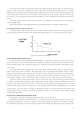


Table Of Contents
- Chapter One Introduction
- Chapter II Technical Specifications
- Chapter IV Panel Operation
- 4.1 Basic operation mode
- 4.2 dynamic test operation
- 4.3 input control
- 4.4 Electronic load operating range
- 4.5 protection function
- 4.6 remote test function
- 4.7 battery discharge test operation
- 4.8 Communication Protocol

17
for each trigger received.
Figure 4.12 Trigger mode of operation
4.2.4 Dynamic test parameter settings
Press the Shift + 6 (S_Tran) button, the load displays "LEVEL A CURR = xxxxxxxxA", prompts the current set A
current value, then press the numeric keys and decimal point key on the panel, enter the desired Value and press
Enter to confirm.
At this moment, the load displays "WIDTH A TM = xxxxxxxxmS" to indicate the current setting A duration. At
this time, you can press the numeric keys and decimal point key on the panel to enter the desired value from high
to low and press Enter key to confirm.
At this time, the load displays "RISING TM = xxxxxxxxmS" to indicate the current setting rising time from A to B.
At this time, you can press the numeric keys and decimal point key on the panel to enter the desired value from
high to low sequentially and press Enter to confirm.
At this time, the load displays "LEVEL B CURR = xxxxxxxxA" to indicate the current setting B current value. At
this time, you can press the numeric keys and decimal point key on the panel to enter the desired value from high
to low and press Enter key to confirm.
At this time, the load displays "WIDTH B TM = xxxxxxxxmS" to indicate the current setting B duration. At this
time, you can press the numeric keys and decimal point key on the panel to enter the desired value from high to
low and press Enter key to confirm.
At this time, the load displays "FALLING TM = xxxxxxxxmS" to indicate the falling time of the current setting
from B to A. Press the numeric keys and decimal point keys on the panel to enter the desired value from high to low
sequentially and press Enter to confirm.
At this time, the load displays "TRANMODE CONTINUOUS" / "TRANMODE PULSE" / "TRANMODE TRIGGER" to
indicate the currently set dynamic test mode. Press ∧ or ∨ key to select the mode you want to set and press
Enter key to confirm.
4.2.5 Waveform control
4.2.5.1 Square wave
If both the rising edge time and the falling edge time are set to 0 and the test mode is set to continuous mode,
the output is a square wave. The output frequency is the reciprocal of the sum of the duration of current A and
current B. Since the minimum fineness is set to 20uS for all times, the load can edit a square wave with a 50% duty
cycle at a maximum frequency of 25KHz.
4.2.5.2 Triangle wave
If the current A and current B duration are set to 0, the test mode is set to continuous mode, the output is a
triangular wave. The output frequency is the reciprocal of the sum of the rising and falling times, so the load can
edit the triangular wave with a maximum frequency of 25KHz, since the minimum fineness set for all times is 20uS.
Since the rising and falling edges of the triangular wave are all staircase waves based on the output frequency of
20uS, the ideal degree of the triangular wave is inversely proportional to the output frequency and may be
equivalent to a square wave in extreme conditions. The rising and falling edges depend on the set time , There are
differences in fineness from 0 to 100 points.