
User Manual
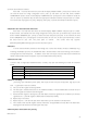
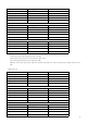
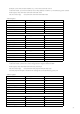

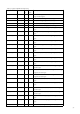
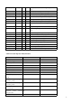
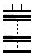
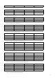
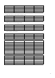
Table Of Contents
- Chapter One Introduction
- Chapter II Technical Specifications
- Chapter IV Panel Operation
- 4.1 Basic operation mode
- 4.2 dynamic test operation
- 4.3 input control
- 4.4 Electronic load operating range
- 4.5 protection function
- 4.6 remote test function
- 4.7 battery discharge test operation
- 4.8 Communication Protocol

28
Check code
2
Abnormal frame
Byte length
value
Additional address
1
1~200
function code
1
0x90
Abnormal code
1
1~4
Check code
2
Example: When the load address is 1, set the constant current value IFIX to 2.3
Table 4.8.7 Table .2 to know the current value IFIX register address is 0x0A01, a 2-word floating-point number
Send request: 0x01 0x10 0x0A 0x01 0x00 0x02 0x04 0x40 0x13 0x33 0x33 0xFC 0x23
Get the normal reply 0x01 0x10 0x0A 0x01 0x00 0x02 0x13 0xD0
4.8.7 Coil and register address assignment
Table 1 coil bit definition:
name
address
Bit
Attrib
utes
Description
PC1
0x0500
1
W/R
Remote control status bit: When 1, the front button
panel is invalid.
PC2
0x0501
1
W/R
Local Prohibit bit: 1, prohibit the use of "Shift + 7"
key to regain control of the front panel.
TRIG
0x0502
1
W/R
Trigger marker bit, software can be set to complete
a trigger.
REMOTE
0x0503
1
W/R
1: Voltage remote input,
ISTATE
0x0510
1
R
Enter the state, 1 for the input ON, 0 for the input
OFF
TRACK
0x0511
1
R
Tracking status, 1 for voltage tracking, 0 for current
tracking
MEMORY
0x0512
1
R
1 is the input status memory
VOICEEN
0x0513
1
R
1 for key sound enable
CONNECT
0x0514
1
R
1 is multi-machine, 0 is single work mode
ATEST
0x0515
1
R
1 is the automatic test mode of operation
ATESTUN
0x0516
1
R
1 Awaiting trigger for automatic test mode of
operation
ATESTPASS
0x0517
1
R
1 for automatic test passed, 0 failed
IOVER
0x0520
1
R
1 is the overcurrent flag
UOVER
0x0521
1
R
1 is over-voltage mark
POVER
0x0522
1
R
1 is over power mark
HEAT
0x0523
1
R
1 is overheating mark
REVERSE
0x0524
1
R
1 for the reverse tag
UNREG
0x0525
1
R
1 is a fixed parameter failure flag
ERREP
0x0526
1
R
1 is the EPPROM error flag
ERRCAL
0x0527
1
R
1 is the calibration data error flag