
User Manual
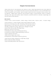
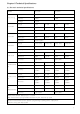

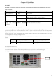
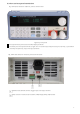
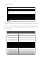
Table Of Contents
- Chapter One Introduction
- Chapter II Technical Specifications
- Chapter IV Panel Operation
- 4.1 Basic operation mode
- 4.2 dynamic test operation
- 4.3 input control
- 4.4 Electronic load operating range
- 4.5 protection function
- 4.6 remote test function
- 4.7 battery discharge test operation
- 4.8 Communication Protocol

5
3.3 front and rear panel introduction
PEL-8000 series electronic load front panel as shown below
Figure 3.2 Front panel
1
The top half of the panel is the black VFD display and knob
2
The lower part of the panel from left to right are 0-9 numeric keys and ESC exit key, function key, up and down
move key and Enter key, input and output terminals.
PEL-8000 series electronic load rear panel as shown below
Remote measurement terminal, trigger input and output interface
Multi-function communication interface, GPIB, RS232, RS425, USB transfer