T3x-05 Treadmill S ER V I C E MA N U A l
Table of Contents CHAPTER 1: Serial number location ............................................................ 1 CHAPTER 2: Important Safety instructions 2.1 2.2 2.4 Before Getting Started ................................................................................................ 2 Read and Save These Instructions ............................................................................. 3 Electrical Requirements ...................................................................................
Table of Contents CHAPTER 9: PART REPLACEMENT GUIDE 9.1 9.2 9.3 9.4 9.5 9.6 9.7 9.8 9.9 9.10 9.11 9.12 9.13 9.14 9.15 9.16 9.17 9.18 9.19 9.20 9.21 Motor Cover Replacement............................................................................................... 32 Rear Roller Replacement ............................................................................................... 33 Side Rail Replacement................................................................................................
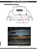
Chapter 1: Serial number Location 1.
Chapter 2: Important Safety Instructions 2.1 Before Getting Started This treadmill is intended for commercial use. To ensure your safety and protect the equipment, read all instructions before operating the Matrix Treadmill. LOCATION OF THE TREADMILL Place the treadmill on a level and stable surface away from direct sunlight. The intense UV light can cause discoloration on the plastics. Locate your treadmill in an area with cool temperatures and low humidity.
Chapter 2: Important safety instructions 2.2 Read and Save these instructions This treadmill is intended for commercial use. To ensure your safety and protect the equipment, read all instructions before operating the MATRIX T3x-05 treadmill. When using an electrical product, basic precautions should always be followed including the following: DANGER: To reduce the risk of electric shock: Always unplug this equipment from the electrical outlet immediately after using and before cleaning.
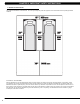
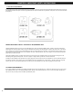
Chapter 2: Important Safety Instructions 2.3 Electrical Requirements For your safety and to ensure good treadmill performance, the ground on this circuit must be non-looped. Please refer to NEC articles 210-21 and 210-23. Your treadmill is provided with a power cord with a plug listed below and requires the listed outlet. Any alterations of this power cord could void all warranties of this product..
Chapter 3: Preventative Maintenance 3.1 recommended cleaning tips In order to maximize life span, and minimize down time, all Matrix Fitness Equipment requires regularly scheduled cleaning. YOU WILL NEED: - Mild dish soap and water mixture in a spray bottle (10:1 water to soap ratio). - Lint free 100% cotton cleaning cloths or Micro fiber cleaning cloths. - Vacuum / Shop Vac with extendable hose and soft brush attachment. DAILY: 1. Wipe down the unit after each use with a mild dish soap and water mixture.
Chapter 3: Preventative maintenance 3.3 Preventative MAINTENANCE instructions In order to maximize life span, and minimize down time, all Matrix Fitness System's equipment requires regular cleaning, and maintenance items performed on a scheduled basis. This section contains detailed instructions on how to perform these items and the frequency of which they should be done.
Chapter 3: Preventative Maintenance 3.4 Auto calibration instructions Run Auto Calibration to calibrate incline after assembly and after replacing any electronic component. AUTO CALIBRATION PROCEDURE: 1) Press and hold the INCLINE DOWN and SPEED DOWN keys for three seconds until Manager appears on the middle LED display. 2) Press the SPEED or INCLINE UP key until Engineering appears on the display. 3) Press ENTER once Engineering is displayed.
Chapter 4: Console Overlay and workout description 4.1 T3x-05 Console Description 8 A) WORKOUT keys: Simple program view and selection buttons. Press Fitness Test button to cycle through available tests. B) GO: One Touch Start. C) ENTER: To confirm each program setting. D) Up / down INCLINE: Adjust incline and make program selections. E) Up / down speed: Adjust speed and make program selections. F) Up / down TIME: Adjust time and make program selections.
Chapter 4: Console overlay and workout description 4.2 Manual Workout Operation QUICK START OPERATION Press the GO button(s) and the treadmill will enter into a manual mode of operation. All energy expenditure values will be calculated using the default weight measurement. MANUAL WORKOUT OPERATION Manual is a workout that allows you to manually adjust the speed and incline values at anytime.
Chapter 4: Console Overlay and workout description 4.4 Heart rate Control Workout Operation Your Matrix T3x-05 Treadmill offers a heart rate control workout mode. The heart rate control workout mode allows the user to program their desired heart rate zone and maximum allowable incline and the treadmill will automatically adjust the incline based upon the user's heart rate. The heart rate zone is calculated using the following equation: (220-Age)*%=target heart rate zone.
Chapter 4: Console overlay and workout description 4.5 Fitness Test workout operation - Continued Sub maximal treadmill evaluation conversion table Stage 1 2.1 2.2 2.3 2.4 3.1 3.2 3.3 3.4 4.1 4.2 4.3 4.4 5.1 5.2 5.3 5.4 6.1 6.2 6.3 6.4 7.1 7.2 7.3 7.4 8.1 8.2 8.3 8.4 9.1 9.2 9.3 9.4 10.1 10.2 10.3 10.4 11.1 11.2 11.3 11.
Chapter 5: Manager Mode 5.1 Using Manager Mode 1) To enter Manager Mode, press & hold INCLINE DOWN and SPEED DOWN keys at the same time for 3-5 seconds until Manager appears on the display. 2) To enter the Manager Mode, press ENTER once Manager Mode appears on the display (Figure A). 3) To scroll between settings in the Manager Mode, press the INCLINE or SPEED keys. 4) Press ENTER to modify the settings once displayed. 5) Press any INCLINE or SPEED key to change the value of the setting.
Chapter 6: Engineering Mode 6.1 USING Engineering mode 1) To enter Engineering Mode, press & hold the INCLINE DOWN and SPEED DOWN keys at the same time for 3-5 seconds until Manager Mode appears on the display. 2) Press the INCLINE or SPEED keys until Engineering Mode appears on the display (Figure A) and press ENTER. 3) To scroll between settings in the Engineering Mode, press the INCLINE or SPEED keys. 4) Press ENTER to modify the settings once displayed.
Chapter 7: Service Mode 7.1 Using Service Mode 1) To enter Service Mode, press & hold the INCLINE DOWN and SPEED DOWN keys at the same time for 3-5 seconds until Manager Mode appears on the display. 2) Press the INCLINE or SPEED keys until Service Mode appears on the display (Figure A) and press ENTER. 3) To scroll between settings in the Service Mode, press the INCLINE or SPEED keys. 4) Press ENTER to modify the settings once displayed. 5) Press any INCLINE or SPEED key to change the value of the setting.
Chapter 8: Troubleshooting 8.
Chapter 8: Troubleshooting 8.
Chapter 8: Troubleshooting 8.
Chapter 8: Troubleshooting 8.
Chapter 8: Troubleshooting 8.3 MCB LED PLACEMENT AND DEFINITIONS PWM - Console PWM signal light (when the motor is running, the light should flash). COM - Digital communication light. FAULT - The machine has stopped due to any C class error. UP / DOWN (FF) - Incline motor status light.
Chapter 8: Troubleshooting 8.4 0140 / 01A0 ERROR TROUBLESHOOTING ERROR MESSAGE 0140 / 01A0 1) cause: a. 0140 – Incline motor operation failure. b. 01A0 – Incline motor disconnection. 2) SOLUTION: a. Check the incline motor wire connection between the incline motor and MCB (Figure A). b. Run Auto Calibration as outlined in Section 3.4. If the problem still exists, refer to the steps below. c. See if a console signal is transmitted to MCB by checking the MCB LED UP and DOWN.
Chapter 8: Troubleshooting 8.5 01A4 / 01A5 / 01A6 ERROR TROUBLESHOOTING ERROR MESSAGE 01A4 / 01A5 / 01A6 1) cause: a. 01A4 - Main motor U phase disconnection. b. 01A5 - Main motor V phase disconnection. c. 01A6 - Main motor W phase disconnection. 2) SOLUTION: a. Check the connection between motor cable and MCB (Figure A). b. Replace the motor. c. Replace the MCB.
Chapter 8: Troubleshooting 8.6 01A8 / 01AD / 02B6 / 02B7 / 02B8 ERROR TROUBLESHOOTING ERROR MESSAGE 01A8 / 01AD / 02B6 / 02B7 / 02B8 1) cause: a. b. c. d. e. 01A8 - Main motor over current of 7 Amps. 01AD - Motor over temperature. 02B6 - Speed up is over current. 02B7 - Speed down is over current. 02B8 - Running status over current. 2) SOLUTION: a. Perform an amp draw (see instruction for how to run an amp draw on Matrix treadmills). Flip the deck or replace the running belt as needed. b.
Chapter 8: Troubleshooting 8.7 01AB ERROR TROUBLESHOOTING ERROR MESSAGE 01AB 1) cause: a. Inverter error. 2) SOLUTION: a. When the display is showing an 01AB error, the MCB Fault LED should be lit (Figure A). b. If the MCB Fault LED is not lit, replace the console. c. If the MCB Fault LED is lit, replace the MCB.
Chapter 8: Troubleshooting 8.8 02A0 / 02A8 ERROR TROUBLESHOOTING ERROR MESSAGE 02A0 / 02A8 1) cause: a. 02A0 - Main motor failure. The belt does not move when it is supposed to move. b. 02A8 - Inverter circuit of the motor failed. Motor resistance is closed. 2) SOLUTION: a. Check the Motor wire connection between the Motor and MCB (Figure A). b. Press the start key and check the MCB PWM LED (Figures B). -- If PWM LED does not flash, replace the console. -- If PWM LED flashes, follow the steps below. c.
Chapter 8: Troubleshooting 8.9 02A1 / 02A2 ERROR TROUBLESHOOTING ERROR MESSAGE 02A1 / 02A2 1) cause: a. 02A1 - Over AC power input voltage. b. 02A2 - Over / low DC bus voltage. 2) SOLUTION: a. Use a multi - meter to check if the input power matches local power specifications at the MCB. Switch to a different outlet if necessary. - If a known good outlet is not providing the correct power, replace the power components as needed. b. If the power input is ok, replace the MCB.
Chapter 8: Troubleshooting 8.10 02AD ERROR TROUBLESHOOTING ERROR MESSAGE 02AD 1) cause: a. MCB over temperature. 2) SOLUTION: a. Check the Motor wire connection between the Motor and MCB (Figure A). b. Use a multi meter to check the for a resistance value across the 2 blue wires of the motor wire (Figure B). -- If there is a resistance value, replace the MCB. -- If there is not a resistance value, replace the motor.
Chapter 8: Troubleshooting 8.11 02B5 ERROR TROUBLESHOOTING ERROR MESSAGE 02B5 1) cause: a. The inverter sensor is reading the normal rated current is over 10.5 amps for 60 seconds. 2) SOLUTION: a. Use a multi - meter to check the 3 points (U / V / W) of the motor cable for resistance over 4Ω (Figures A, B & C). -- If yes, replace the motor. -- If no, flip the deck and / or replace the running belt. b. Replace the MCB if all other solutions fail.
Chapter 8: Troubleshooting 8.12 02B9 / 02BA / 02BC / 02BD ERROR TROUBLESHOOTING ERROR MESSAGE 02B9 / 02BA / 02BC / 02BD 1) cause: a. b. c. d. 02B9 - The inner memory IC data write error. 02BA - The inner memory IC data read error. 02BC - Ground connection or fuse error. 02BD - Inverter hardware interrupt error. 2) SOLUTION: a. Replace the MCB.
Chapter 8: Troubleshooting 8.13 04A0 ERROR Troubleshooting ERROR MESSAGE 04A0 1) cause: a. PCB communication disconnected. 2) SOLUTION: a. b. c. d. Check the console cable connection between the UCB and MCB (Figures A & B). Replace the console cable if any damage is found. Replace the console if the connections are good. Replace the MCB if all other solutions fail.
Chapter 8: Troubleshooting 8.14 04B0 ERROR Troubleshooting ERROR MESSAGE 04B0 1) cause: a. MCB communication disconnected. 2) SOLUTION: a. b. c. d. Check the console cable connection between the UCB and MCB (Figures A & B). Replace the console cable if any damage is found. Replace the console if the connections are good. Replace the MCB if all other solutions fail.
Chapter 8: Troubleshooting 8.15 troubleshooting - Heart Rate issues HEart Rate Issues 1) SYMPTOM: a. No heart rate. b. High or irratic heart rate. 2) SOLUTION: a. With a multi meter set for DC Voltage, place one prong of the multi meter on each of the HR plates on the handlebar (Figure A). A correctly connected HR grip will have a DC Voltage reading of between 0.5 and 2.0. If this reading is correct, skip to Step b.
Chapter 9: Part Replacement Guide 9.1 Motor Cover RePLacement 1) Remove the 2 screws holding the motor cover to the frame using a 6 mm Allen wrench (Figures A). 2) The motor cover is secured to the frame with velcro, so you will have to pull up with some force (Figure B). Figure A Figure B 3) Figure C shows the motor area with the cover removed. 4) Reverse Steps 1-2 to install a new motor cover. NOTE: When reinstalling the motor cover, be sure to tuck the sides in so they do not bow outward (Figure D).
Chapter 9: Part Replacement Guide 9.2 REAR ROLLER REPLACEMENT 1) Remove one of the rear end caps using a Phillips screwdriver (Figure A). 2) Remove both roller adjustment screws using an 8 mm Allen wrench (Figure B). Figure A Figure B 3) Remove the rear roller from the running belt (Figures C & D). Figure C Figure D 4) Reverse Steps 1-3 to install a new rear roller. 5) Test the treadmill for function as outlined in Section 9.21.
Chapter 9: Part Replacement Guide 9.3 SIDE RAIL REPLACEMENT 1) Remove the rear end cap using a Phillips screwdriver (Figure A). 2) Loosen the four screws under the frame using a 5 mm Allen wrench (Figure B). Figure A Figure B 3) Slide the rail off the back of the treadmill (Figures C & D). Figure C Figure D 4) Reverse Steps 1-3 to install a new side rail. NOTE: After reinstalling the side rail, make sure the rear end cap is on first before tightening the screws for proper gap spacing.
Chapter 9: Part Replacement Guide 9.4 RUNNING DECK REPLACEMENT 1) Remove the motor cover as outlined in Section 9.1. 2) Remove the side rail as outlined in Section 9.3. 3) Remove the four running deck screws using a 5 mm Allen wrench (Figure A). Figure A 4) Remove the running deck from the running belt (Figures B & C). Figure B Figure C 5) Reverse Steps 1-4 to install a new running deck. NOTE: The running deck is waxed on both sides so the opposite side surface may be usable.
Chapter 9: Part Replacement Guide 9.5 DECK CUSHION REPLACEMENT 1) Remove the deck as outlined in Section 9.4. 2) Holding the bolt with a 5 mm Allen wrench, loosen the nut with a 13 mm socket (Figure A & B). Figure A Figure B 3) For the rear cushion, hold the cushion and remove the 13 mm nut (Figure C). Figure C 4) Reverse Steps 1-3 to install new deck cushions. 5) Test the treadmill for function as outlined in Section 9.21.
Chapter 9: Part Replacement Guide 9.6 FRONT ROLLER REPLACEMENT 1) Remove the motor cover as outlined in Section 9.1. 2) Loosen both of the rear roller screws using an 8mm T-Shaped wrench to remove tension from the running belt (Figure A). 3) Remove the front roller mounting screws using an 6 mm Allen wrench (Figures B & C). Figure A Figure B Figure C 4) Use a hook or loop of wire to remove the spring from the drive belt tensioner. The tensioner should now pivot away from the drive belt (Figure D).
Chapter 9: Part Replacement Guide 9.7 RUNNING BELT REPLACEMENT 1) 2) 3) 4) 5) Remove Remove Remove Remove Remove the the the the the motor cover as outlined in Section 9.1. rear roller as outlined in Section 9.2. running deck as outlined in Section 9.4. front roller as outlined in Section 9.6. running belt (Figures A). Figure A 6) Reverse Steps 1-5 to install a new running belt.
Chapter 9: Part Replacement Guide 9.8 MOTOR CONTROL BOARD (MCB) REPLACEMENT 1) 2) 3) 4) Turn off power and disconnect the cord from the machine. Remove the motor cover as outlined in Section 9.1. Disconnect the wire connectors at the MCB. Remove the 2 screws holding each side of the MCB to the frame (Figures A & B). Figure A Figure B 5) Remove the MCB (Figure C). 6) Reverse Steps 1-5 to install a new MCB. Make sure that all wires removed during Step 3 are re-connected.
Chapter 9: Part Replacement Guide 9.9 MOTOR REPLACEMENT 1) 2) 3) 4) Turn off power to the treadmill and disconnect the power cord. Remove the motor cover as outlined in Section 9.1. Use a hook or loop of wire to remove the spring from the drive belt tensioner (Figure A). Remove the drive belt tensioner using a 6 mm Allen wrench (Figure B) Figure A Figure B 5) Cut any wire ties holding the motor cable to the frame (Figure C). 6) Disconnect the motor cable ground wire from the grounding post (Figure D).
Chapter 9: Part Replacement Guide 9.9 MOTOR REPLACEMENT - CONTINUED 7) Disconnect the motor cable from the MCB (Figure E). 8) Remove the 4 screws holding the motor to the frame (Figure F). 9) Remove the motor from the treadmill. figure e figure f 10) Reverse Steps 1-9 to install a new motor. NOTE: Be sure that the motor isolator pad is in place prior to mounting the new motor (Figure G). figure G 11) Test the treadmill for function as outlined in Section 9.21.
Chapter 9: Part Replacement Guide 9.10 DRIVE BELT REPLACEMENT 1) 2) 3) 4) Turn off power to the treadmill and disconnect the power cord. Remove the motor cover as outlined in Section 9.1. Use a hook or loop of wire to remove the spring from the drive belt tensioner (Figure A). The tensioner should now pivot away from the drive belt (Figure B) Figure A Figure B 5) With the tension on the drive belt relieved it can be walked off of the motor pulley (Figure C).
Chapter 9: Part Replacement Guide 9.10 DRIVE BELT REPLACEMENT - CONTINUED 7) Remove the two 8 mm screws from front roller (Figures E & F). Figure E Figure F 8) Lift the roller and remove the old drive belt (Figure G). Figure G 9) Reverse Steps 1-8 to install a new drive belt. NOTE: After installing a new belt, check it for correct alignment to the motor pulley before setting the tensioner in place. 10) Test the treadmill for function as outlined in Section 9.21.
Chapter 9: Part Replacement Guide 9.11 INCLINE MOTOR REMOVAL 1) 2) 3) 4) Turn off power to the treadmill and disconnect the power cord. Remove the motor cover as outlined in Section 9.1. Lift the treadmill and support it so that the front wheels are off the floor, or the unit may be tipped on its side (Figure A). Remove the cotter pin from the elevation rack pin (Figure B). Figure A Figure B 5) Remove the elevation rack pin (Figure C). 6) Disconnect the incline motor power cable from the MCB (Figure D).
Chapter 9: Part Replacement Guide 9.11 Incline Motor RePLACEMENT - continued 7) Remove the incline motor cable ground wire from the ground prong in the motor frame (Figure E). 8) Disconnect the incline motor from the top mounting bracket (Figure F). Figure E Figure F 9) Lift the incline motor away from the treadmill (Figure G). 10) Reverse Steps 1-9 to install a new incline motor.
Chapter 9: Part Replacement Guide 9.12 CONSOLE REPLACEMENT 1) Turn off power to the treadmill and disconnect the power cord. 2) Remove the 2 screws holding the back cover onto the console (Figure A). 3) Remove the 4 screws holding the console onto the console frame (Figure B). Figure A Figure B 4) Disconnect the 6 wire connections from the console (Figure C). 5) Remove the console (Figure D). FIGURE C 6) Reverse Steps 1-5 to install a new console.
Chapter 9: Part Replacement Guide 9.13 EMERGENCY STOP SWITCH REPLACEMENT 1) 2) 3) 4) Turn off power to the treadmill and remove the power cord. Remove the console as outlined in Section 9.12. Remove the 2 screws holding the emergency stop key to the emergency stop frame (Figure A). Remove the 2 screws holding the emergency stop frame to the console frame (Figure B). FIGURE A FIGURE B 5) Use a flat screwdriver to flex the emergency stop key to remove it from the emergency stop frame (Figures C & D).
Chapter 9: Part Replacement Guide 9.13 EMERGENCY STOP SWITCH REPLACEMENT - CONTINUED 6) Disconnect the 2 wires plugged into the back of the emergency stop switch (Figure E). 7) Depress the tabs on the top and the bottom of the emergency stop switch (Figure F). Figure E Figure F 8) Once the tabs are depressed, the emergency stop can be removed from the emergency stop frame (Figure G). 9) Reverse Steps 1-8 to install a new emergency stop switch.
Chapter 9: Part REplacement Guide 9.14 CUP HOLDER REPLACEMENT 1) Remove the console as outlined in Section 9.12. 2) Remove the 3 screws holding the cup holder to the console frame (Figure A & B) FIGURE B FIGURE A 3) Remove the cup holder (Figure C). Figure C 4) Reverse Steps 1-3 to install a new cup holder.
Chapter 9: Part Replacement Guide 9.15 console frame replacement 1) 2) 3) 4) Turn off power to the treadmill and disconnect the power cord. Remove the console as outlined in Section 9.12. Remove the 2 screws on each side holding the console frame to the handlebar frame (Figure A). Remove the 3 screws on each side holding the cup holder to the console frame (Figure B) FIGURE A FIGURE B 5) Remove the 2 cup holders from console frame (Figure C).
Chapter 9: Part Replacement Guide 9.15 console frame replacement - CONTINUED 7) Remove the console frame (Figure E). FIGURE E 8) Reverse Steps 1-7 to install a new console frame. 9) Test the treadmill for function as outlined in Section 9.21.
Chapter 9: Part Replacement Guide 9.16 heart rate board replacement 1) Turn off power to the treadmill and remove the power cord. 2) Remove the console as outlined in Section 9.12. 3) Disconnect the wire connections that go to the heart rate board (Figure A & B). figure a Figure B 4) Depress the 4 spacer supports holding the heart rate board to the console frame and remove it (Figure C). Figure C 5) Reverse Steps 1-4 to install a new heart rate board.
Chapter 9: Part Replacement Guide 9.17 HANDLEBAR FRAME REPLACEMENT 1) 2) 3) 4) Turn off power to the treadmill and remove the power cord. Remove the console as outlined in Section 9.12. Remove the console frame as outlined in Section 9.15 Remove the 3 screws on each side holding the handlebar frame to the console mast (Figure A). figure a 5) Lift the handlebar frame up and away from the console mast (Figure B).
Chapter 9: Part Replacement Guide 9.18 heart rate handlebar replacement 1) Turn off power to the treadmill and remove the power cord. 2) Remove the console as outlined in Section 9.12. 3) Remove the console frame as outlined in Section 9.15. 4) Remove the 3 screws on each side holding the handlebar frame to the console mast (Figure A). 5) Lift the handlebar frame up and away from the console mast (Figure B).
Chapter 9: Part Replacement Guide 9.19 Heart rate Grips Replacement 1) Turn off power to the treadmill and remove the power cord. 2) Remove the 2 Phillips screws holding the 2 halves of the HR grip together (Figure A). 3) Disconnect the white wire from the bottom HR terminal and remove it (Figure B). Figure B Figure A 4) Disconnect the red wire from the top HR terminal and remove it (Figure C). Figure C 5) Reverse Steps 1-4 to install new HR grips.
Chapter 9: Part Replacement Guide 9.20 CONSOLE MAST REPLACEMENT 1) 2) 3) 4) 5) 6) Turn off power to the treadmill and remove the power cord. Remove the console as outlined in Section 9.12. Remove the console frame as outlined in Section 9.15. Remove the handlebar frame as outlined in Section 9.17. Remove the motor cover as outlined in Section 9.1. Remove the 4 screws holding the console mast to the base frame (Figure A). Figure A 7) Remove the console mast.
Chapter 9: Part Replacement Guide 9.21 testing the treadmill Once the treadmill or replacement part is fully installed and assembled and properly placed on the floor, use the following instructions to setup and test the machine: 1) If the treadmill was just assembled or if any electronic component has been replaced (including if the console cable is unplugged for any reason), the treadmill MUST be auto calibrated. Refer to the procedure in Section 3.4.
Chapter 10: Treadmill specifications and assembly guide 10.1 TREADMILL SPECIFICATIONS model name T-3x model type T3x Treadmill frame part # T3X-04-F console part # T-3X-04-C Features Deck Type Ultimate™ Hard-Wax reversible 1" deck Belt Type Habasit - 2-ply commercial grade Running area 60” X 20” / 152.4 CM X 50.8 CM Deck Step Height 7.5” / 19.1 CM Cushion System Ultimate Deck™ Cushioning System Incline Range 0%-15% (1,300 LB / 589.7 KG THRUST INCLINE MOTOR) Speed Range 0.5 - 12.
Chapter 10: Treadmill specifications and assembly Guide 10.2 Fasteners and Assembly tools frame set CONSOLE SET part # part name 41 Hex Head Cap Screw diagram specification quantity color M8 x 1.
Chapter 10: Treadmill specifications and assembly guide 10.3 ASSEMBLY INSTRUCTIONS ATTENTION After assembly and installation is complete, the treadmill will need to be calibrated using the auto-calibration procedure outlined in Section 3.4. DO NOT stand on the belt while the auto-calibration sequence is in progress. Prior to assembling the treadmill, unpack all of the contents of the box and make sure that all necessary components are present. Review the contents of the hardware package for completeness.
Chapter 10: Treadmill specifications and assembly Guide 10.3 ASSEMBLY INSTRUCTIONS - CONTINUED STEP 3 A Open yellow and white hardware bags. B Assemble the contact HR crossbar to the left and right handlebars using 18-button head screw. Fasten the contact HR crossbar/handlebar assembly to the console masts using 15-button head screw and 12-flat washer. Note: Make sure the arrows on the mast rings are pointing upward towards the console when sliding into place.
Chapter 10: Treadmill specifications and assembly guide 10.3 ASSEMBLY INSTRUCTIONS - CONTINUED STEP 4 STEP 5 T1xe/T3xe shown T1xe/T3xe shown A A Open black hardware bag. B Assemble the console to the handlebars using 14-socket head cap screw. Be sure to route the console cables down the console mast and connect the contact HR wires. Make all appropriate wire connections within the motor Re-assemble motor cover to treadmill base using pre-attached screws.
Chapter 10: Treadmill specifications and assembly guide 10.4 MYE TV Bracket Installation instructions 1) Remove the 2 screws holding the console back cover on and remove the back cover (Figures A & B). Figure A Figure B 2) Use a razor to remove the existing HR overlay on the console (Figure C). 3) Slide the ribbon cable of the entertainment keypad / overlay through the slot in the console (Figure D).
Chapter 10: Treadmill specifications and assembly guide 10.4 MYE TV Bracket Installation Instructions - Continued 6) Mount the TV bracket to the frame using 4 socket head screws sent with the bracket kit (Figure G). 7) Remove the blank head phone plate from the front of the console. 8) Install the new headphone jack, plastic, and wiring into the console (Figure H). Figure G Figure H 9) Plug the headphone wire into the MYE TV port on the translator board (Figure I).
Chapter 10: Treadmill specifications and assembly guide 10.4 MYE TV Bracket Installation instructions - Continued 13) Connect the coax extension cable to the cable coming from the base of the unit (Figure M). 14) Mount the TV to the bracket using 4 screws sent with the TV (Figure N). Figure M Figure N 15) Make sure that the tabs on the front plate are tucked behind the console faceplate to create a seamless look (Figure O). 16) Plug the coax cable into the port on the TV (Figure P).
Chapter 10: Treadmill specifications and assembly guide 10.4 MYE TV Bracket Installation Instructions - Continued 19) Plug the TV controller wire into the MYE TV port on the translator board (Figure S). Plug the other side of TV controller wire into the port on the TV (Figure T). Figure S Figure T 20) Install the console back cover removed in Step 2 (Figure U).
Chapter 10: Treadmill specifications and assembly guide 10.4 MYE TV Bracket Installation instructions - Continued 23) Plug the TV power wire into the port at the base of the treadmill (Figure Y). 24) A channel scan should be done using the instructions included in the TV owner's manual.
Chapter 10: Treadmill specifications and assembly guide 10.5 PCTV Bracket Installation instructions 1) Remove the 2 screws holding the console back cover on and remove the back cover (Figures A & B). Figure A Figure B 2) Cut the wire tie holding the coax cable, power wire, net wire, and controller wire to the console frame (Figure C). 3) Mount the TV bracket to the frame using 4 socket head screws sent with the bracket kit (Figure D).
Chapter 10: Treadmill specifications and assembly guide 10.5 PCTV Bracket Installation Instructions - Continued 7) Mount the front plate to the TV using 2 screws sent with the bracket kit (Figure G). 8) Connect the power wire extension wire to the power wire coming from the base of the unit (Figure H).
Chapter 10: Treadmill specifications and assembly guide 10.5 PCTV Bracket Installation instructions - CONTINUED NOTE: The wire connections in Steps 12 - 15 should be done prior to installing the TV onto the bracket as the bracket will prevent some of the connections from being made. 12) Plug the coax cable into the port on the TV (Figure M). 13) Plug the power wire into the port on the TV (Figure N). Figure M Figure N 14) Plug the controller wire into the port on the TV (Figure O).
Chapter 10: Treadmill specifications and assembly guide 10.5 PCTV Bracket Installation Instructions - Continued 18) Mount the TV to the bracket using 4 screws sent with the TV (Figure S). 19) Make sure that the tabs on the front plate are tucked behind the console faceplate to create a seamless look (Figure T). Figure S Figure T 20) Install the console back cover removed in Step 2 (Figure U).
Chapter 10: Treadmill specifications and assembly guide 10.5 PCTV Bracket Installation instructions - Continued 23) Plug the TV power wire into the port at the base of the treadmill (Figure Y). 24) Plug a network cable into the port at the base of the treadmill is using wired internet (Figure Z). Figure Y 25) The PCTV should now be programmed as outlined in the PCTV owner's or service manuals.
Chapter 11: Software Upgrade guide 11.1 software upgrade instructions 1. Create an access on the USB flash drive which will be used. The access should be MATRIX\FW\UCB (create a folder called MATRIX, then a folder in MATRIX called FW, then a folder in FW called UCB). Or you can put the USB flash drive into the console and hold the PAUSE and Manual keys on the keypad for 3 second and the USB flash drive will automatically be formatted (Figure A). 2.
NOTES 74
MATr i x F i tne ss s y st e m s c o r p. 1610 Landmark D rive C ottage G rove wi 5 3 5 2 7 U S A TO LL FREE 866. 693. 4 8 6 3 w w w. m a t r i x f i t n e s s . c o m FA X 6 0 8 . 8 3 9 . 1 7 1 7 REV.