T3x-02 (TopTech MCB) Treadmill S ER V ICE M A N U A l
Table of Contents CHAPTER 1: Serial number location . .......................................................... 1 CHAPTER 2: Important Safety instructions 2.1 2.3 2.4 Before Getting Started ................................................................................................ 2 Read and Save These Instructions ............................................................................ 3 Electrical Requirements .....................................................................................
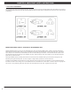
Table of Contents CHAPTER 9: PART REPLACEMENT GUIDE 9.1 9.2 9.3 9.4 9.5 9.6 9.7 9.8 9.9 9.10 9.11 9.12 9.13 9.14 9.15 9.16 9.17 9.18 9.19 9.20 9.21 Motor Cover Replacement........................................................................................... 29 Rear Roller Replacement............................................................................................. 30 Running Deck Removal...............................................................................................
Chapter 1: Serial number Location 1.
Chapter 2: Important Safety Instructions 2.1 Before Getting Started This treadmill is intended for commercial use. To ensure your safety and protect the equipment, read all instructions before operating the Matrix Treadmill. Please leave a 78.75" (2000 mm) x 39.50" (1000 mm) landing zone behind the treadmill. This zone is to allow easy access to the treadmill and gives the user an easy exit path from the machine.
Chapter 2: Important safety instructions 2.2 Read and Save these instructions This treadmill is intended for commercial use. To ensure your safety and protect the equipment, read all instructions before operating the MATRIX T3x-02 treadmill. When using an electrical product, basic precautions should always be followed including the following: DANGER: To reduce the risk of electric shock: Always unplug this equipment from the electrical outlet immediately after using and before cleaning.
Chapter 2: Important Safety Instructions 2.3 Electrical Requirements For your safety and to ensure good treadmill performance, the ground on this circuit must be non-looped. Please refer to NEC articles 210-21 and 210-23. Your treadmill is provided with a power cord with a plug listed below and requires the listed outlet. Any alterations of this power cord could void all warranties of this product..
Chapter 3: Preventative Maintenance 3.1 recommended cleaning tips 3.2 Check for damaged parts Preventative maintenance and daily cleaning will prolong the life and look of your MATRIX T3x-02 Treadmill. DO NOT use any equipment that is damaged or has worn or broken parts. Use only replacement parts supplied by Matrix Fitness Systems. Please read and follow these tips. • P osition the equipment away from direct sunlight. The intense UV light can cause discoloration on plastics.
Chapter 3: Preventative maintenance 3.3 Care and MAINTENANCE instructions In order to maximize life span, and minimize down time, all Matrix Fitness System's equipment requires regular cleaning, and maintenance items performed on a scheduled basis. This section contains detailed instructions on how to perform these items and the frequency of which they should be done.
Chapter 3: Preventative Maintenance 3.4 Auto calibration instructions Run Auto Calibration to calibrate incline after assembly and after replacing any electronic component. AUTO CALIBRATION PROCEDURE: 1) Press and hold the INCLINE DOWN and SPEED DOWN keys for three seconds until Manager appears on the middle LED display. 2) Press the SPEED or INCLINE UP key until Engineering appears on the display. 3) Press ENTER once Engineering is displayed.
Chapter 3: Preventative maintenance 3.6 KNOWING WHEN TO REPLACE THE RUNNING BELT AND DECK One of the most common wear and tear items on a treadmill is the deck and belt combination. If these two items are not properly maintained, they can cause damage to other components. Always keep your deck and belt free of dirt and dust by wiping the edges of the belt and deck and up to 2" under the belt with a clean dry cloth.
Chapter 4: Console Overlay and workout description 4.1 T3x-02 Console Description WORKOUT KEYS: Simple program view and selection buttons. GO: One touch Start and Quick Start. ENTER: To confirm each program setting. UP / DOWN INCLINE: Easy information and incline selection. UP / DOWN SPEED: Easy information and speed selection. EMERGENCY STOP / IMMOBILIZATION: To stop all functions and immobilize the unit.
Chapter 4: Console overlay and workout description 4.2 Manual Workout Operation QUICK START OPERATION Press the GO button(s) and the treadmill will enter into a manual mode of operation. All energy expenditure values will be calculated using the default weight measurement. MANUAL WORKOUT OPERATION Manual is a workout that allows you to manually adjust the speed and incline values at anytime.
Chapter 4: Console Overlay and workout description 4.4 Heart rate Control Workout Operation Your Matrix T3x-02 Treadmill offers a heart rate control workout mode. The heart rate control workout mode allows the user to program their desired heart rate zone and maximum allowable incline and the treadmill will automatically adjust the incline based upon the user's heart rate. The heart rate zone is calculated using the following equation: (220-Age)*%=target heart rate zone.
Chapter 4: Console overlay and workout description 4.5 Fitness Test workout operation - Continued Sub maximal treadmill evaluation conversion table Stage 1 2.1 2.2 2.3 2.4 3.1 3.2 3.3 3.4 4.1 4.2 4.3 4.4 5.1 5.2 5.3 5.4 6.1 6.2 6.3 6.4 7.1 7.2 7.3 7.4 8.1 8.2 8.3 8.4 9.1 9.2 9.3 9.4 10.1 10.2 10.3 10.4 11.1 11.2 11.3 11.
Chapter 5: Manager Mode 5.1 Using Manager Mode 1) on 2) 3) 4) 5) 6) 7) To enter Manager Mode, press & hold INCLINE DOWN and SPEED DOWN keys at the same time for 3-5 seconds until Manager appears the display. To enter the Manager Mode, press ENTER once Manager Mode appears on the display (Figure A). To scroll between settings in the Manager Mode, press the INCLINE or SPEED keys. Press ENTER to modify the settings once displayed. Press any INCLINE or SPEED key to change the value of the setting.
Chapter 6: Engineering Mode 6.1 USING Engineering mode 1) To enter Engineering Mode, press & hold the INCLINE DOWN and SPEED DOWN keys at the same time for 3-5 seconds until Manager Mode appears on the display. 2) Press the INCLINE or SPEED keys until Engineering Mode appears on the display (Figure A) and press ENTER. 3) To scroll between settings in the Engineering Mode, press the INCLINE or SPEED keys. 4) Press ENTER to modify the settings once displayed.
Chapter 7: Service Mode 7.1 Using Service Mode 1) To enter Service Mode, press & hold the INCLINE DOWN and SPEED DOWN keys at the same time for 3-5 seconds until Manager Mode appears on the display. 2) Press the INCLINE or SPEED keys until Service Mode appears on the display (Figure A) and press ENTER. 3) To scroll between settings in the Service Mode, press the INCLINE or SPEED keys. 4) Press ENTER to modify the settings once displayed. 5) Press any INCLINE or SPEED key to change the value of the setting.
Chapter 8: Troubleshooting 8.
Chapter 8: Troubleshooting 8.
Chapter 8: Troubleshooting 8.
Chapter 8: Troubleshooting 8.3 MCB LED PLACEMENT AND DEFINITIONS PWM - Console PWM signal light (when the motor is running, the light should flash). COM - Digital communication light. FAULT - The machine has stopped due to any C class error. UP / DOWN (FF) - Incline motor status light.
Chapter 8: Troubleshooting 8.4 ERROR MESSAGES ON THE CONSOLE CLASS LEVEL ERROR CODE DESCRIPTION CONDITION B 0140 Incline motor fail. When the incline motor is supposed to move, it does not move. When the error happens the incline motor will be locked. The command "initialize" is needed to unlock the incline. C 01A0 Incline motor disconnection. When the incline position cable is not connected. C 01A4 Main motor U phase disconnection. Main motor U phase disconnection.
Chapter 8: Troubleshooting 8.5 0140 / 01A0 ERROR TROUBLESHOOTING ERROR MESSAGE 0140 / 01A0 1) cause: a. Incline motor operation failed. 2) SOLUTION: a. Check the connection of the incline motor cable at the MCB. b. Run auto calibration (See Section 3.5). c. If auto calibration fails, press GO and attempt to incline the treadmill. - Check the MCB UP and DOWN (FF) LEDs (Figure A). If the LEDs do not light up when incline is commanded, replace the console cable or console.
Chapter 8: Troubleshooting 8.6 01A4 / 01A5 / 01A6 ERROR TROUBLESHOOTING ERROR MESSAGE 01A4 / 01A5 / 01A6 1) cause: a. 01A4 - Main motor U phase disconnection. b. 01A5 - Main motor V phase disconnection. c. 01A6 - Main motor W phase disconnection. 2) SOLUTION: a. Check the connection of the motor cable at the MCB (Figure A). b. Replace the motor. c. Replace the MCB. FIGURE A U V 8.
Chapter 8: Troubleshooting 8.8 01AB ERROR TROUBLESHOOTING ERROR MESSAGE 01AB 1) cause: a. Inverter error. 2) SOLUTION: a. When the display is showing an 01AB error, the MCB Fault LED should be lit (Figure A). b. If the MCB Fault LED is not lit, replace the console. c. If the MCB Fault LED is lit, replace the MCB.
Chapter 8: Troubleshooting 8.9 02A0 / 02A8 ERROR TROUBLESHOOTING ERROR MESSAGE 02A0 / 02A8 1) cause: a. 02A0 - Main motor failure. The belt does not move when it is supposed to move. b. 02A8 - Inverter circuit of the motor failed. Motor resistance is closed. 2) SOLUTION: a. b. c. d. 24 Check the connection of the motor cable at the MCB (Figure A). Use a multi - meter to check the motor cable for resistance at 3 points (Figures B, C, & D). If the motor cable displays an ohm value, replace the MCB.
Chapter 8: Troubleshooting 8.10 02A1 / 02A2 ERROR TROUBLESHOOTING ERROR MESSAGE 02A1 / 02A2 1) cause: a. 02A1 - Over AC power input voltage. b. 02A2 - Over / low DC bus voltage. 2) SOLUTION: a. Use a multi - meter to check if the input power is over 260V. b. If the power outlet is ok, replace the MCB. 8.11 02AD ERROR TROUBLESHOOTING ERROR MESSAGE 02AD 1) cause: a. MCB over temperature. 2) SOLUTION: a. b. c. d. Check the condition and connection of the motor cable at the MCB (Figure A).
Chapter 8: Troubleshooting 8.12 02B5 ERROR TROUBLESHOOTING ERROR MESSAGE 02B5 1) cause: a. The inverter sensor is reading the normal rated current is over 10.5 amps for 60 seconds. 2) SOLUTION: a. Use a multi - meter to check the motor cable for resistance at 3 points (Figures A, B, & C). b. If the motor cable displays an ohm value over 4, replace the motor. c. If the motor cable displays an ohm value under 4, replace the MCB.
Chapter 8: Troubleshooting 8.13 02B9 / 02BA / 02BC / 02BD ERROR TROUBLESHOOTING ERROR MESSAGE 02B9 / 02BA / 02BC / 02BD 1) cause: a. b. c. d. 02B9 - The inner memory IC data write error. 02BA - The inner memory IC data read error. 02BC - Ground connection or fuse error. 02BD - Inverter hardware interrupt error. 2) SOLUTION: a. Replace the MCB. 8.14 04A0 ERROR Troubleshooting ERROR MESSAGE 04A0 1) cause: a. No communication response. 2) SOLUTION: a. b. c. d. e.
Chapter 8: Troubleshooting 8.15 troubleshooting - Heart Rate issues heart rate function does not work or is reading incorrectly possible causes: 1) 2) 3) 4) 5) 6) The The The The The The chest strap being used is not making good contact with the user's chest. chest strap is at a low battery status. chest strap is damaged. HR grips are damaged. HR board is damaged. UCB is damaged. SOLUTION: 1) Re-center the chest strap below the user's pectoral muscle (Figure A) and check again.
Chapter 9: Part Replacement Guide 9.1 Motor Cover RePLacement 1) Remove the 2 screws holding the motor cover to the frame using a 6 mm Allen wrench (Figures A). 2) The motor cover is velcroed to the frame, so you will have to pull up with some force (Figure B). Figure A Figure B 3) Figure C shows the motor area with the cover removed. 4) Reverse Steps 1-2 to install a new motor cover. NOTE: When reinstalling the motor cover, be sure to tuck the sides in so they do not bow outward (Figure D).
Chapter 9: Part Replacement Guide 9.2 REAR ROLLER REPLACEMENT 1) Remove one of the rear end caps using a Phillips screwdriver (Figure A). 2) Remove both rear roller adjustment screws using an 8 mm Allen wrench (Figure B). Figure A Figure B 3) Remove the rear roller from the running belt (Figures C & D). Figure C Figure D 4) Reverse Steps 1-3 to install a new roller. NOTE: Be sure to follow the instructions in Section 3.5 to re-tension the running belt.
Chapter 9: Part Replacement Guide 9.3 DECK REMOVAL 1) Remove the motor cover as outlined in Section 9.1. 2) Remove the four deck screws using a 5 mm Allen wrench (Figure A). Figure A 3) Remove the deck from the running belt (Figures B & C). Figure B 4) 5) 6) 7) Figure C Be careful not to pinch fingers during removal / installation of deck board. Deck is waxed on both sides so the opposite side surface may be usable. New deck surfaces must ALWAYS be matched to a new running belt.
Chapter 9: Part Replacement Guide 9.4 DECK CUSHION REPLACEMENT 1) Remove the deck as outlined in Section 9.3. 2) Holding the bolt with a 5 mm Allen wrench, loosen the nut with a 13 mm socket (Figure A & B). Figure A Figure B 3) For the rear cushion, hold the cushion and remove the 13 mm nut (Figure C). Figure C 4) Reverse Steps 1-3 to install new deck cushions. 5) Test the treadmill for function as outlined in Section 9.21.
Chapter 9: Part Replacement Guide 9.5 FRONT ROLLER REPLACEMENT 1) Remove the motor cover as outlined in Section 9.1. 2) Using a hook or loop of wire, remove the spring from the drive belt tensioner. The tensioner should now pivot away from the drive belt (Figure A). 3) Loosen the rear roller screws to remove tension from the running belt. 4) Remove the front roller mounting screws using an 8 mm Allen wrench (Figures B & C).
Chapter 9: Part Replacement Guide 9.6 RUNNING BELT REPLACEMENT 1) Remove the motor cover as outlined in Section 9.1. 2) Remove the rear roller as outlined in Section 9.2. 3) Remove the deck as outlined in Section 9.3. 4) Remove the front roller as outlined in Section 9.5. 5) Remove the running belt and replace it with a new belt (Figures A & B). NOTE: New running belts should ALWAYS be installed on a new deck surface (deck should either be flipped or replaced to gain a new surface).
Chapter 9: Part Replacement Guide 9.7 SIDE RAIL REPLACEMENT 1) Remove the rear end cap using a Phillips screwdriver (Figure A). 2) Loosen the four screws under the frame using a 5 mm Allen wrench (Figure B). Figure A Figure B 3) Slide the rail off the back of the treadmill (Figures C & D). Figure C Figure D 4) Reverse Steps 1-3 to install a new side rail. 5) After reinstalling the side rail, make sure the rear end cap is on first before tightening the screws for proper gap spacing.
Chapter 9: Part Replacement Guide 9.8 MOTOR CONTROL BOARD (MCB) REPLACEMENT 1) 2) 3) 4) Turn off power and disconnect the cord from the machine. Remove the motor cover as outlined in Section 9.1. Remove the wire connections to the MCB. Remove the 2 screws holding the MCB to the base frame (Figures A & B). Figure A Figure B 5) Remove the MCB. 6) Reverse Steps 1-5 to install a new MCB. NOTE: Be sure to plug in all wire connections removed in Step 3 (Figure C).
Chapter 9: Part Replacement Guide 9.9 MOTOR REPLACEMENT 1) 2) 3) 4) Turn off power to the treadmill and disconnect the power cord. Remove the motor cover as outlined in Section 9.1. Release the drive belt tensioner spring (Figure A). With the spring released, rotate the tensioner to relieve tension on the drive belt (Figure B). Figure A Figure B 5) The drive belt can now be walked off of the motor pulley (Figure C).
Chapter 9: Part Replacement Guide 9.9 MOTOR REPLACEMENT - CONTINUED 7) Disconnect the motor ground wire from the motor and cut any tie straps holding the ground wire in place (Figure E). figure e 8) Using an 8 mm Allen wrench, remove the four motor mounting screws (Figure F). 9) Lift the motor away from the treadmill (Figure G). figure f figure g 10) Reverse Steps 1-9 to install a new motor. NOTE: The speed sensor on the motor is not used on this model and should not be plugged into the MCB.
Chapter 9: Part Replacement Guide 9.10 DRIVE BELT REPLACEMENT 1) Turn off power to the treadmill and disconnect the power cord. 2) Remove the motor cover as outlined in Section 9.1. 3) Release the drive belt tensioner spring (Figure A). Figure A 4) With the spring released, rotate the tensioner to relieve tension on the drive belt and walk the drive belt off of the motor pulley (Figures B & C).
Chapter 9: Part Replacement Guide 9.10 DRIVE BELT REPLACEMENT - CONTINUED 5) Loosen the rear roller screws to relieve tension on the running belt (Figure D). 6) Remove the two 8 mm front roller screws (Figures E & F). 7) Lift the roller and remove the old drive belt (Figure G). Figure D Figure E 8) Reverse Steps 1-7 to install a new drive belt. NOTE: After installing a new belt, check it for correct alignment to the motor pulley before setting the tensioner in place.
Chapter 9: Part Replacement Guide 9.11 INCLINE MOTOR REPLACEMENT 1) Turn off power to the treadmill and disconnect the power cord. 2) Lift the treadmill and support it so that the front wheels are off the floor, or the unit may be tipped on its side (Figure A). Figure A 3) Remove the clip from the pin and remove the pin attaching the incline motor to the rack (Figure B & C).
Chapter 9: Part Replacement Guide 9.11 Incline Motor RePLACEMENT - continued 4) Disconnect the incline motor power cable from the MCB (Figure D). 5) Disconnect the incline motor from the top mounting bracket (Figure E). Figure D Figure E 6) Lift the incline motor away from the treadmill (Figure F). 7) Reverse Steps 1-6 to install a new incline motor. NOTE: When installing the new incline motor, make sure to replace the white washers at the top and bottom (Figure G).
Chapter 9: Part Replacement Guide 9.12 CONSOLE REPLACEMENT 1) 2) 3) 4) Turn off power to the treadmill and disconnect the power cord. Remove the four 6 mm screws from underneath the console (Figure A). Disconnect the 4 electrical connectors to the console. Remove the console (Figure B). Figure A Figure B 5) Reverse Steps 1-4 to install a new console. NOTE: Be sure to plug in the 4 wires disconnected in Step 3 (Figure C). FIGURE C 6) Test the treadmill for function as outlined in Section 9.21.
Chapter 9: Part Replacement Guide 9.13 EMERGENCY STOP SWITCH REPLACEMENT 1) 2) 3) 4) Turn off power to the treadmill and remove the power cord. Remove the console as outlined in Section 9.12. Remove the 2 screws holding the red emergency stop key to the emergency stop frame (Figure A). Remove the 2 screws holding the emergency stop frame to the console frame (Figure B).
Chapter 9: Part Replacement Guide 9.13 EMERGENCY STOP SWITCH REPLACEMENT - CONTINUED 6) Disconnect the 2 wires plugged into the back of the emergency stop switch (Figure E). 7) Depress the tabs on the top and the bottom of the emergency stop switch (Figure F). Figure E Figure F 8) This will allow the emergency stop to be removed from the emergency stop frame (Figure G). 9) Reverse Steps 1-8 to install a new emergency stop switch.
Chapter 9: Part Replacement Guide 9.14 console frame replacement 1) Turn off power to the treadmill and disconnect the power cord. 2) Remove the console as outlined in Section 9.12. 3) Remove the 2 screws on each side holding the console frame to the handlebar frame (Figure A). figure A 4) Remove the console frame from the handlebar frame. NOTE: The console cable wiring will need to be removed from the console frame as it is removed (Figure B). Figure B 5) Reverse Steps 1-4 to install a new console frame.
Chapter 9: Part Replacement Guide 9.15 heart rate board replacement 1) Turn off power to the treadmill and remove the power cord. 2) Remove the console as outlined in Section 9.12. 3) Remove the console frame as outlined in Section 9.14. 4) Remove the 2 screws holding the emergency stop frame to the console frame (Figure A). 5) Lay the console frame on its face and remove the 7 screws holding the back panel to the console frame and lean the console back out of the way (Figure B).
Chapter 9: Part Replacement Guide 9.16 speed or incline keypad replacement 1) Turn off power to the treadmill and remove the power cord. 2) Remove the console as outlined in Section 9.12. 3) Remove the console frame as outlined in Section 9.14. 4) Remove the 2 screws holding the emergency stop frame to the console frame (Figure A). 5) Lay the console frame on its face and remove the 7 screws holding the back panel to the console frame and lean the console back out of the way (Figure B).
Chapter 9: Part Replacement Guide 9.17 HANDLEBAR FRAME REPLACEMENT 1) 2) 3) 4) Turn off power to the treadmill and remove the power cord. Remove the console as outlined in Section 9.12. Remove the console frame as outlined in Section 9.14. Remove the 3 screws on each side holding the handlebar frame to the console mast (Figure A). figure a 5) Lift the handlebar frame up and away from the console mast (Figure B).
Chapter 9: Part Replacement Guide 9.18 heart rate handlebar replacement 1) Turn off power to the treadmill and remove the power cord. 2) Remove the console as outlined in Section 9.12. 3) Remove the console frame as outlined in Section 9.14. 4) Remove the 3 screws on each side holding the handlebar frame to the console mast (Figure A). 5) Lift the handlebar frame up and away from the console mast (Figure B).
Chapter 9: Part Replacement Guide 9.19 Heart rate Grips Replacement 1) Turn off power to the treadmill and remove the power cord. 2) Remove the 2 Phillips screws holding the 2 halves of the HR grip together (Figure A). 3) Disconnect the white wire from the bottom HR terminal and remove it (Figure B). Figure B Figure A 4) Disconnect the red wire from the top HR terminal and remove it (Figure C). Figure C 5) Reverse Steps 1-4 to install new HR grips.
Chapter 9: Part Replacement Guide 9.20 CONSOLE MAST REPLACEMENT 1) Turn off power to the treadmill and remove the power cord. 2) Remove the console as outlined in Section 9.12. 3) Remove the console frame as outlined in Section 9.14. 4) Remove the handlebar frame as outlined in Section 9.17. 5) Remove the motor cover as outlined in Section 9.1. 6) Remove the 4 screws holding the console mast to the base frame (Figure A). 7) Remove the console mast.
Chapter 9: Part Replacement Guide 9.21 testing the treadmill Once the treadmill or replacement part is fully installed and assembled and properly placed on the floor, use the following instructions to setup and test the machine: 1) If the treadmill was just assembled or if any electronic component has been replaced (including if the console cable is unplugged for any reason), the treadmill MUST be auto calibrated. Refer to the procedure in Section 3.4.
Chapter 10: Treadmill specifications and assembly guide 10.1 TREADMILL SPECIFICATIONS FEATURES Deck Type Ultimate Hard-Wax reversible 1" deck Belt Type Habisat - 2 ply commercial grade Running Area 60" x 20" Deck Step Height 7.5" Cushion System Ultimate Deck Cushioning System Incline Range 0 - 15% (1300 lb. thrust incline motor) Speed Range 0.5 - 12 mph / 0.8 - 20 km/h Contact HR Sensors Yes Telemetric HR Receiver Yes Transport Wheels Yes DRIVE SYSTEM Motor Matrix 4.
Chapter 10: Treadmill specifications and assembly Guide 10.2 Fasteners and Assembly tools frame set part # part name diagram specification quantity color 11 Hex Head Cap Screw M8 x 1.25P x 25L 8 Blue 12 Flat Washer 8.2 x 19 2.0t 8 Blue 13 Hex Head Cap Screw M8 x 1.25P x 15L 6 Black 14 Button Head Screw M8 x 1.25P x 25L 6 White 15 Flat Washer 8.2 x 19 x 2.0t 6 White CONSOLE SET part # part name 41 Hex Head Cap Screw diagram specification quantity color M8 x 1.
Chapter 10: Treadmill specifications and assembly guide 10.3 ASSEMBLY INSTRUCTIONS ATTENTION After assembly and installation is complete, the treadmill will need to be calibrated using the auto-calibration procedure outlined in Section 3.4. DO NOT stand on the belt while the auto-calibration sequence is in progress. Prior to assembling the treadmill, unpack all of the contents of the box and make sure that all necessary components are present. Review the contents of the hardware package for completeness.
Chapter 10: Treadmill specifications and assembly Guide 10.3 ASSEMBLY INSTRUCTIONS - CONTINUED Open Black & White Assembly Bag. Assemble the HR handlebar to the left and right handlebars using item 14 - hex head cap screw. Fasten the contact HR handlebar assembly to the console masts using item 15 - button head screw and item 12 - flat washer. Pull the HR wires through the handlebar using the wire pull. Pull the mast wire through the handlebar.
Chapter 10: Treadmill specifications and assembly guide 10.3 ASSEMBLY INSTRUCTIONS - CONTINUED Open Black Assembly Bag. Assemble the console frame to the handlebars using item 14 - hex head cap screw. Be sure to route the console cables down the console mast and connect the HR handlebar wires. Make all appropriate wire connections within the motor compartment. Open Yellow Console Assembly Bag.
Chapter 10: Treadmill specifications and assembly Guide 10.3 Assembly instructions - continued Open Green Assembly Bag. Install the power cord and assemble item 18 power cord holder with item 22 button head screw. If your hardware pack is missing item 22, check to see if the screws are already assembled on the treadmill. Replace the motor cover(s) and power the treadmill on. The power button is located next to the power cord inlet.
Chapter 11: Software Upgrade guide 11.1 software upgrade instructions 1) Copy the file named SRPDJMVH onto a USB drive. 2) Turn off the treadmill power. 3) Insert the USB drive into the Reprogram Port of the T3x-02 console back cover (Figure A). 4) Turn on the treadmill power. The machine will make 3 short beep sounds and should start to upgrade the software. 5) Once the upgrade is complete, the machine will make 2 long beep sounds (should take about 30 seconds).
NOTES 61
M ATri x F i tne ss s y st e ms c o r p. 1610 La ndmark Drive C otta g e Grove wi 5 3 5 2 7 U S A TO LL FREE 866. 693. 4863 w w w. m a t r i x f i t n e s s . c o m KO REV. 1 62 FA X 6 0 8 . 8 3 9 .