T7XE-03 TREADMILL SERVICE MANUAL
TABLE OF CONTENTS CHAPTER 1: SERIAL NUMBER LOCATION . .................................................................. 1 CHAPTER 2: IMPORTANT SAFETY INSTRUCTIONS 2.1 2.2 2.3 2.4 Legal Disclaimer.......................................................................................................... Before Getting Started ............................................................................................... Read and Save These Instructions . ....................................................
TABLE OF CONTENTS 8.11 8.12 8.13 8.14 8.15 8.16 8.17 8.18 8.19 8.20 02B9 / 02BA / 02BD Error Troubleshooting................................................................ 04A0 Error Troubleshooting........................................................................................ Troubleshooting - No Power to the Console . ............................................................ Troubleshooting - Heart Rate Issues..........................................................................
CHAPTER 1: SERIAL NUMBER LOCATION 1.
CHAPTER 2: IMPORTANT SAFETY INFORMATION 2.1 BEFORE GETTING STARTED This treadmill is intended for commercial use. To ensure your safety and protect the equipment, read all instructions before operating the Matrix Treadmill. Please leave a 78.75" (2000 mm) x 39.50" (1000 mm) landing zone behind the treadmill. This zone is to allow easy access to the treadmill and gives the user an easy exit path from the machine.
CHAPTER 2: IMPORTANT SAFETY INSTRUCTIONS 2.2 READ AND SAVE THESE INSTRUCTIONS This treadmill is intended for commercial use. To ensure your safety and protect the equipment, read all instructions before operating the MATRIX T7x-03 treadmill. When using an electrical product, basic precautions should always be followed including the following: DANGER: To reduce the risk of electric shock: Always unplug this equipment from the electrical outlet immediately after using and before cleaning.
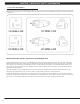
CHAPTER 2: IMPORTANT SAFETY INFORMATION 2.3 ELECTRICAL REQUIREMENTS For your safety and to ensure good treadmill performance, the ground on this circuit must be non-looped. Please refer to NEC article 210-21 and 210-23. Your treadmill is provided with a power cord with a plug listed below and requires the listed outlet. Any alterations of this power cord could void all warranties of this product..
CHAPTER 3: PREVENTATIVE MAINTENANCE 3.1 RECOMMENDED CLEANING TIPS Preventative maintenance and daily cleaning will prolong the life and look of your MATRIX treadmill. Please read and follow these tips. • P osition the equipment away from direct sunlight. The intense UV light can cause discoloration on plastics. • L ocate your equipment in an area with cool temperatures and low humidity. • Clean with a soft 100% cotton cloth.
CHAPTER 3: PREVENTATIVE MAINTENANCE 3.3 CARE AND MAINTENANCE INSTRUCTIONS In order to maximize life span, and minimize down time, all Matrix Fitness System's equipment requires regular cleaning, and maintenance items performed on a scheduled basis. This section contains detailed instructions on how to perform these items, the frequency of which they should be done, and a check list to sign off on each time service is completed for a specific machine.
CHAPTER 3: PREVENTATIVE MAINTENANCE 3.4 TOUCH SCREEN CARE & CLEANING TOUCH SCREEN CARE AND CLEANING * The touch screen requires very little maintenance. We recommend that you periodically clean the touch screen surface with a dry soft cloth. If necessary, we recommend the usage of Alcohol or Isopropyl Alcohol for difficult stains or sanitary purposes. * It is very important to avoid using any other chemical on the touch screen. * Always dampen the cloth and clean the screen.
CHAPTER 3: PREVENTATIVE MAINTENANCE 3.5 AUTO CALIBRATION INSTRUCTIONS Run Auto Calibration to calibrate incline after assembly and after replacing any electronic component. AUTO CALIBRATION PROCEDURE: 1) Press "ENTER, 2, 0, 0, 1, ENTER". Engineering Mode will appear on the display. 2) CALIBRATION and AUTO CALIBRATION should be already highlighted. You just need to press the START button (Figure A). You SHOULD NOT be standing on the unit while it is calibrating.
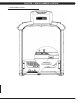
CHAPTER 4: CONSOLE OVERLAY AND WORKOUT DESCRIPTION 4.1 T7XE-03 CONSOLE DESCRIPTION The Matrix treadmill is inspected before it is packaged. It is shipped in four pieces: the base, the upright console supports, the handlebar, and the console. Carefully unpack the unit and dispose of the box material. The T7xe-03 has a fully integrated touch screen display. All information required for workouts is explained on screen. Exploration of the interface is highly encouraged.
CHAPTER 4: CONSOLE OVERLAY AND WORKOUT DESCRIPTION 4.2 MANUAL WORKOUT OPERATION QUICK START OPERATION Press the GO or QUICK START button(s) and the treadmill will count down "3, 2, 1" and enter into a manual mode of operation. All energy expenditure values will be calculated using the default weight measurement. 4.3 OPERATING LEVEL BASED PROGRAMS Your Matrix treadmill offers a variety of level-based workouts to challenge users of all fitness levels.
CHAPTER 4: CONSOLE OVERLAY AND WORKOUT DESCRIPTION 4.4 HEART RATE CONTROL WORKOUT OPERATION Your Matrix treadmill offers a heart rate control workout mode. The heart rate control workout mode allows the user to program their desired heart rate zone and maximum allowable incline and the treadmill will automatically adjust the incline based upon the user's heart rate. The heart rate zone is calculated using the following equation: (220-Age)*%=target heart rate zone.
CHAPTER 4: CONSOLE OVERLAY AND WORKOUT DESCRIPTION 4.5 FITNESS TEST WORKOUT OPERATION - CONTINUED SUBMAXIMAL TREADMILL EVALUATION CONVERSION TABLE Stage 1 2.1 2.2 2.3 2.4 3.1 3.2 3.3 3.4 4.1 4.2 4.3 4.4 5.1 5.2 5.3 5.4 6.1 6.2 6.3 6.4 7.1 7.2 7.3 7.4 8.1 8.2 8.3 8.4 9.1 9.2 9.3 9.4 10.1 10.2 10.3 10.4 11.1 11.2 11.3 11.
CHAPTER 5: MANAGER MODE 5.1 USING MANAGER MODE 1) To enter Manager Mode, press "ENTER 1001 ENTER" on the number keypad and Manager Mode will appear on the display. 2) Manager Mode is divided into 6 tabs, located on the left side of the screen. They are About, Time, Speed, Defaults, TV, and Language. 3) Choose a tab by touching the screen over the desired tab. 4) Each of the tabs have options that will appear once you have chosen that particular tab.
CHAPTER 5: MANAGER MODE 5.2 MANAGER MODE - TAB 1 T7xe-02-C - If the unit has the old MMM board, the CSafe Model should be set for Off. 14 T7xe-03-C - If the unit has the LMM board, the CSafe Model should be set for On. MANAGER MODE FUNCTION & DEFAULTS About Serial Number This option displays the serial number of the platform and console, not editable (see Service Mode to change serial numbers). DESCRIPTIONS Cannot be modified.
CHAPTER 5: MANAGER MODE 5.3 MANAGER MODE - TAB 2 MANAGER MODE Time FUNCTION & DEFAULTS DESCRIPTIONS MODIFIED Maximum Time Default: 60 Minutes This option enables clubs to set the maximum workout duration limits during peak and non peak hours of traffic. Maximum: 99 Minutes Minimum: 5 Minutes Default Time Default: 30 Minutes This option controls the default program time. Maximum: Maximum Time Minimum: 5 Minutes Pause Time Default: 5 Minutes This option controls the default pause time.
CHAPTER 5: MANAGER MODE 5.5 MANAGER MODE - TAB 4 MANAGER MODE Defaults 16 FUNCTION & DEFAULTS DESCRIPTIONS MODIFIED Default Level Default: 1 This option controls the default program levels. Maximum: 20 Minimum: 1 Default Age Default: 30 This option controls the default user's age used in the target heart rate calculations. Maximum: 100 Minimum: 10 Default Weight Default: 150 lb / 68 kg This option controls the default weight used in the calorie calculations.
CHAPTER 5: MANAGER MODE 5.6 MANAGER MODE - TAB 5 MANAGER MODE TV FUNCTION & DEFAULTS DESCRIPTIONS MODIFIED Default Channel Default: 3 This option controls the default TV channel on start up. Maximum: 99 Minimum: 1 Default Volume Default: 5 This option controls the default TV volume on start up. Maximum: 17 Minimum: 0 Tuner Available Default: Yes This option controls the default TV function. If NO is selected, the TV tab will be removed from the normal function.
CHAPTER 5: MANAGER MODE 5.7 MANAGER MODE - TAB 6 MANAGER MODE LANGUAGE ENGLISH FUNCTION & DEFAULTS Default Language Language FLAG DESCRIPTIONS This option allow the user to select the flag for the specific language shown on the display.
CHAPTER 5: MANAGER MODE 5.8 MANAGER MODE - TAB 7 MANAGER MODE Other FUNCTION & DEFAULTS DESCRIPTIONS MODIFIED Altitude Default: 5000 ft This option controls the default altitude used in the fitness test score calculations. Asset Management Default: Off This option allows the fitness club to collect the machine data to a PC server. ON or OFF Virtual Active Default: ON This option controls the Virtual Active function.
CHAPTER 6: ENGINEERING MODE 6.1 USING ENGINEERING MODE 1) To enter Engineering Mode, press "ENTER 2001 ENTER" on the number keypad and Engineering Mode will appear on the display. 2) Engineering Mode is divided into 5 tabs, located on the left side of the screen. They are Calibration, Statistics, Errors, Clubs, and Club ID. 3) Choose a tab by touching the screen over the desired tab. 4) Each of the tabs have options that will appear once you have chosen that particular tab.
CHAPTER 6: ENGINEERING MODE 6.3 ENGINEERING MODE - TAB 2 ENGINEERING MODE FUNCTION & DEFAULTS Statistics DESCRIPTIONS This option displays workout information for the various programs. MODIFIED N/A 6.4 ENGINEERING MODE - TAB 3 ENGINEERING MODE FUNCTION & DEFAULTS Errors DESCRIPTIONS This option displays the error code history on the treadmill.
CHAPTER 6: ENGINEERING MODE 6.5 ENGINEERING MODE - TAB 4 ENGINEERING MODE FUNCTION & DEFAULTS Clubs Default: MATRIX DESCRIPTIONS This option allows the user to select the screen header from a list. MODIFIED N/A 6.6 ENGINEERING MODE - TAB 5 ENGINEERING MODE FUNCTION & DEFAULTS Club ID 22 DESCRIPTIONS This option records the club ID of the fitness facility.
CHAPTER 7: SERVICE MODE 7.1 USING SERVICE MODE 1) To enter Service Mode, press "ENTER 3001 ENTER" on the number keypad and Service Mode will appear on the display. 2) Service Mode is divided into 4 tabs, located on the left side of the screen. They are Setup, Test, Log, and Date & Time. 3) Choose a tab by touching the screen over the desired tab. 4) Each of the tabs have options that will appear once you have chosen that particular tab.
CHAPTER 7: SERVICE MODE 7.3 SERVICE MODE - TAB 2 SERVICE MODE Test 24 FUNCTION & DEFAULTS DESCRIPTIONS MODIFIED Keypad This option is for a keypad test. N/A Touch Calibration This option allows for a touch calibration of the console. Follow the cross mark and touch the screen to catch. After 5 positions are tested, touch the center of the screen to exit this test. N/A Keypad Type Default: No Quick Start This option sets the type of keypad for the treadmill.
CHAPTER 7: SERVICE MODE 7.4 SERVICE MODE - TAB 3 SERVICE MODE FUNCTION & DEFAULTS Log DESCRIPTIONS This option allows the club to record key components replacement history. MODIFIED N/A 7.5 SERVICE MODE - TAB 4 SERVICE MODE FUNCTION & DEFAULTS Date & Time DESCRIPTIONS This option allows the club to set the current date and time.
CHAPTER 8: TROUBLESHOOTING 8.
CHAPTER 8: TROUBLESHOOTING 8.
CHAPTER 8: TROUBLESHOOTING 8.
CHAPTER 8: TROUBLESHOOTING 8.
CHAPTER 8: TROUBLESHOOTING 8.2 MCB LED INSTRUCTIONS LED RS485 MCU DOWN UP +12V 30 REFERENCE DESIGNATOR DESCRIPTION DSP2 Indicates if the digital communication is working normally between the console and the MCB. Blinking = Normal. Off = Fault DSP1 Indicates if the console is working normally. Blinking - Normal. Light = MCU Fault. Off = MCU No Power. DSP5 Indicates if the console is commanding elevation down. Light = Normal. Off - No command from console received by the elevation motor.
CHAPTER 8: TROUBLESHOOTING 8.
CHAPTER 8: TROUBLESHOOTING 8.4 ERROR MESSAGES ON THE CONSOLE CLASS LEVEL ERROR CODE DESCRIPTION B 0140 Incline motor operation fail. B 0141 Motor over temperature. C 01A0 Incline motor is disconnected. C 01A2 Incline motor is detected in the reverse of the position indicated by the potentiometer. C 01A3 Motor is disconnected. C 01A8 Motor over current. C 01AB Inverter Error. C 01AD Motor over loading. B 0241 Lower DC bus voltage. B 029F Generic Class B Error.
CHAPTER 8: TROUBLESHOOTING 8.5 0140 / 01A0 / 01A2 ERROR TROUBLESHOOTING ERROR MESSAGES 0140 / 01A0 / 01A2 1) SYMPTOM: a. 0140 - Incline motor operation failed. b. 01A0 - Incline motor disconnected. c. 01A2 - Incline motor is detected in the reverse of the position indicated by the potentiometer. 2) SOLUTION a. Check the connection of the incline motor cable at the MCB. b. Run auto calibration (See Section 3.5). c. If auto calibration fails, re-enter Engineering Mode and again go to Calibration.
CHAPTER 8: TROUBLESHOOTING 8.6 01A3 ERROR TROUBLESHOOTING ERROR MESSAGE 01A3 1) SYMPTOM: a. Motor is disconnected. 2) SOLUTION: a. b. c. d. e. Check the connection of the motor cable at the MCB (Figure A). Check to see if the MCB LED DSP1 (MCU) is lit (Figure B). If LED DSP1 is blinking, the motor should be replaced. If LED DSP1 is a solid light, replace the motor. If LED DSP1 is not lit, replace the MCB. FIGURE A FIGURE B 8.
CHAPTER 8: TROUBLESHOOTING 8.8 01AD ERROR TROUBLESHOOTING ERROR MESSAGE 0X029F 1) SYMPTOM: a. Motor over temperature. 2) SOLUTION: a. Check the connection of the motor cable at the MCB (Figure A). b. Use a multi-meter to check the motor wire circuit. Set the multi-meter to Ohms and place both terminals on the blue wires of the motor cable (Figure B). There should be an Ohm reading of 0. If there is an Ohm reading above 0, replace the motor. If the Ohm reading is 0, replace the MCB.
CHAPTER 8: TROUBLESHOOTING 8.10 02B2 ERROR TROUBLESHOOTING ERROR MESSAGE 02B2 1) SYMPTOM: a. The emergency circuit on the interface board active. 2) SOLUTION: switch. a. Check the connection of the safety key (emergency stop) switch (Figure A). If the switch is always open or shorted out, replace the b. If the emergency stop does not resolve the issue, replace the console. FIGURE A 8.11 02B9 / 02BA / 02BD ERROR TROUBLESHOOTING ERROR MESSAGE 02B9 / 02BA / 02BD 1) SYMPTOM: a.
CHAPTER 8: TROUBLESHOOTING 8.12 04A0 ERROR TROUBLESHOOTING ERROR MESSAGE 04A0 1) SYMPTOM: a. No communication received. 2) SOLUTION: a. If the display is giving an 04A0 error, LED DSP2 (RS485) should be off (Figure A). If this light is not on and an 04A0 error is present, replace the console. b. Check the connection of the console communication cable at both the console and the MCB. c. Replace the console communication cable. d. Replace the MCB.
CHAPTER 8: TROUBLESHOOTING 8.13 TROUBLESHOOTING - NO POWER TO THE CONSOLE POWER SWITCH IS ON, BUT THE CONSOLE HAS NO DISPLAY 1) SYMPTOM: a. The unit is not getting power from the outlet. b. The MCB is not getting power from the power receptacle. c & d. The power switch and MCB LEDs are lit, but there is no power to the console. 2) SOLUTION: a. Check to see if the power switch is lit. If it is not, plug the power cord into a known working outlet and re-test.
CHAPTER 8: TROUBLESHOOTING 8.14 TROUBLESHOOTING - HEART RATE ISSUES HEART RATE ISSUES 1) SYMPTOM: a. The display is stuck on heart rate. b. Erratic heart rate. c. No heart rate. 2) SOLUTION: a. If the display is stuck on heart rate, it is normally due to the lighting in the workout area. - Change the lighting in the area of the treadmill. - Move the treadmill to a different area. - Also check to make sure that nobody is using a telemetric heart rate strap in the area. b.
CHAPTER 8: TROUBLESHOOTING 8.15 TROUBLESHOOTING - DISPLAY COLOR ISSUES CONSOLE DISPLAY COLOR ISSUES 1) SYMPTOM: a. The display colors are off or there are a "rainbow" of colors on the display. 2) SOLUTION: a. Check the console cable connections at the upper and lower control boards. b. Check the LED display wire connection (Figure A). - This wire connection should be taped in place, add tape if needed. - This wire should be tie strapped to the frame (Figure B). Add a tie strap if needed.
CHAPTER 8: TROUBLESHOOTING 8.16 TROUBLESHOOTING - SPEED SHOWN IS SLOWER THAN BELT SPEED SCREEN SHOWS A HIGH SPEED, BUT THE BELT MOVING SLOWER THAN SHOWN 1) SYMPTOM: a. The unit speed does not match the console display. 2) SOLUTION: a. Perform an amp draw on the incoming power (see Field Work Instruction - Running an Amp Draw on Matrix Treadmills). b. If the amp draw is too high regardless if a user is present or not, the issue is likely with the drive system (drive belt or motor).
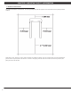
CHAPTER 8: TROUBLESHOOTING 8.17 ENTERTAINMENT TROUBLESHOOTING - OVERVIEW 1. Sections 8.17 - 8.20 will help with diagnosing problems with TV and entertainment related equipment that is produced by Matrix Fitness. 2. The Matrix T7xe treadmill includes an integrated TV that shows in the large display window. The TV is capable of being shown as a 7" or 15" screen (Figures A & B). Your treadmill should be equipped with an Entertainment keypad similar to Figure C.
CHAPTER 8: TROUBLESHOOTING 8.18 ENTERTAINMENT TROUBLESHOOTING – PICTURE FUZZY OR UNCLEAR 1. Using a verified good piece of coax cable (a good coax cable will have a signal strength of 10hz or greater), remove the console back cover (Figure A) and hook the coax directly to the TV jack on the tuner. This bypasses internal connections for your machine (Figure B). 2. Check your internal cables and fittings inside your machine at the console (Figure B) and below the motor cover (Figure C).
CHAPTER 8: TROUBLESHOOTING 8.19 ENTERTAINMENT TROUBLESHOOTING -TV WILL NOT TURN ON 1. If you have no picture at all, check to see if you have any status lights on your Entertainment keypad (next to the power button). The status light should be red when off or in standby mode, and green when the TV is powered on. If you have lights of any color skip to Section 8.20. 2. Remove the console back (Figure A) and check the electrical connections for the TV (Figures B & C). 3.
CHAPTER 8: TROUBLESHOOTING 8.20 ENTERTAINMENT TROUBLESHOOTING - ENTERTAINMENT KEYPAD ISSUES 1. If you have a status light on the Entertainment keypad but the On/Off button gives no response, disconnect and then reconnect the power to the treadmill from the wall. Attempt to turn on the TV again using the On/Off button. 2. If TV still does not power on, remove the console back (Figure A) and check the Entertainment keypad connections at the console (Figure B). 3.
CHAPTER 9: PART REPLACEMENT GUIDE 9.1 MOTOR COVER AND LOWER SHROUD REMOVAL 1) The motor cover is split into two pieces (called the motor cover and lower shroud 2) Remove the 2 screws holding motor cover to the frame (Figure A ). 3) Pull up on the rear of the motor cover to release the Velcro, and remove the motor cover (Figure B). FIGURE A FIGURE B 4) Remove the 4 screws holding the lower shroud to the frame (Figure C). 5) Figure D shows a unit with both the motor cover and lower shroud removed.
CHAPTER 9: PART REPLACEMENT GUIDE 9.2 REAR ROLLER REPLACEMENT 1) Turn off power to the unit and disconnect the cord from the machine. 2) Remove one of the end caps using a Phillips screwdriver (Figure A). 3) Remove both roller adjustment screws using an 8 mm Allen wrench (Figure B). FIGURE A FIGURE B 4) Remove the roller from the running belt (Figures C & D). FIGURE C FIGURE D 5) Reverse Steps 1-4 to install a new rear roller. 6) Tension the running belt as outlined in Section 3.6.
CHAPTER 9: PART REPLACEMENT GUIDE 9.3 RUNNING DECK REPLACEMENT 1) Remove the motor cover as outlined in Section 9.1. 2) Remove the four running deck screws using a 5 mm Allen wrench (Figure A). FIGURE A 3) Remove the running deck from the running belt (Figures B & C). NOTE: Be careful not to pinch fingers during removal / installation of the running deck. FIGURE B FIGURE C 4) Reverse Steps 1-3 to install a new running deck.
CHAPTER 9: PART REPLACEMENT GUIDE 9.4 RUNNING DECK CUSHION REPLACEMENT 1) Remove the running deck as outlined in Section 9.3. 2) Hold the running deck cushion bolt with a 5 mm Allen wrench and loosen the nut with 13 mm socket (Figure A & B). FIGURE A FIGURE B 3) Remove the rear cushion by holding the cushion while removing the 13 mm nut (Figure C). FIGURE C 4) Reverse Steps 1-3 to install new running deck cushions. 5) Tension the running belt as outlined in Section 3.6.
CHAPTER 9: PART REPLACEMENT GUIDE 9.5 FRONT ROLLER REPLACEMENT 1) Remove the motor cover as outlined in Section 9.1. 2) Using a hook or loop of wire, remove the spring from the drive belt tensioner. The tensioner should now pivot away from the drive belt (Figures A & B). FIGURE A FIGURE B 3) Remove the front roller mounting screws using an 8 mm Allen wrench (Figures C & D). 4) Remove the drive belt from the front roller and remove the roller from the running belt (Figure E).
CHAPTER 9: PART REPLACEMENT GUIDE 9.6 RUNNING BELT REPLACEMENT 1) 2) 3) 4) 5) Remove the motor cover as outlined in Section 9.1. Remove the rear roller as outlined in Section 9.2. Remove the running deck as outlined in Section 9.3. Remove the front roller as outlined in Section 9.5. Once the rollers and deck are removed, the running belt can be lifted up and off the unit (Figures A & B). FIGURE A FIGURE B 6) Reverse Steps 1-5 to install a new running belt.
CHAPTER 9: PART REPLACEMENT GUIDE 9.7 SIDE RAIL REPLACEMENT 1) Remove the 4 screws holding on the end cap on the same side as the broken side rail using a Phillips screwdriver and remove the end cap (Figure A). 2) Loosen the four screws under the frame of the side rail using a 5 mm Allen wrench (Figure B). FIGURE A FIGURE B 3) Slide the rail off the back of the treadmill (Figures C & D). FIGURE C FIGURE D 4) Reverse Steps 1-3 to install a new side rail.
CHAPTER 9: PART REPLACEMENT GUIDE 9.8 MOTOR CONTROL BOARD (MCB) REPLACEMENT 1) 2) 3) 4) 5) Turn off power and disconnect the cord from the machine. Remove the motor cover as outlined in Section 9.1. Cut any wire ties that are secured to the MCB panel. Disconnect wires from the MCB - five total connections. Remove two MCB mounting screws using a Phillips head screwdriver (Figures A & B). FIGURE B FIGURE A 6) Reverse Steps 1-5 to install a new MCB.
CHAPTER 9: PART REPLACEMENT GUIDE 9.9 MOTOR REPLACEMENT 1) 2) 3) 4) 5) Turn off the power and disconnect the cord from the machine. Remove the motor cover as outlined in Section 9.1. Release the drive belt tensioner as outlined in Section 9.5. Disconnect the motor power cable from the MCB (Figure A). Use an 8 mm Allen wrench to remove the four motor mounting screws (Figure B). FIGURE A FIGURE B 6) Lift the motor away from the treadmill (Figure C). 7) Reverse Steps 1-6 to install a new motor.
CHAPTER 9: PART REPLACEMENT GUIDE 9.10 DRIVE BELT REPLACEMENT 1) Remove the motor cover as outlined in Section 9.1. 2) Release the drive belt tensioner from the drive belt as outlined in Section 9.5. 3) Remove the front roller screw on the drive belt side and loosen the screw on the opposite side (Figure A). FIGURE A 4) Lift the roller and remove the old drive belt (Figure B). FIGURE B 5) Reverse Steps 1-4 to install a new drive belt.
CHAPTER 9: PART REPLACEMENT GUIDE 9.11 INCLINE MOTOR REPLACEMENT 1) Turn off the power and disconnect the cord from the machine. 2) Lift the treadmill and support it so that the front wheels are off the floor, or the unit may be tipped on its side (Figure A). FIGURE A 3) Remove the clip from the pin attaching the bottom of the incline motor to the rack (Figure B). 4) Remove the pin attaching the bottom of the incline motor to the rack (Figure C).
CHAPTER 9: PART REPLACEMENT GUIDE 9.11 INCLINE MOTOR REPLACEMENT - CONTINUED 5) Disconnect the incline motor power cable from the MCB (Figure D). 6) Disconnect the pin from the top of the incline motor (Figure E). FIGURE D FIGURE E 7) Lift the incline motor away from the treadmill (Figure F). 8) Reverse Steps 1-7 to install a new incline motor. When installing the new motor, the worm screw should be turned as short as possible, and then rotated out 2 full turns prior to being re-attached to the rack.
CHAPTER 9: PART REPLACEMENT GUIDE 9.12 CONSOLE REMOVAL 1) 2) 3) 4) Turn off the power and disconnect the cord from the machine. Remove the 4 screws holding the console back to the front (Figure A). Lean the console back away from the console and disconnect the coax cable connection. Remove the six 6 mm screws from underneath the console. There are arrows stamped in the plastic at the proper openings (Figure B).
CHAPTER 9: PART REPLACEMENT GUIDE 9.13 CONSOLE MAST ARM REPLACEMENT 1) 2) 3) 4) Turn off power and disconnect the cord from the machine. Remove the console as outlined in Section 9.12. Take off the cup holder from the right side of the treadmill (Figure A). Use a 6 mm Allen wrench to remove one screw and take off the plastic hand rail (Figure B). FIGURE A FIGURE B 5) Remove the 5 Phillips screws and remove the right side upper plastic cover (Figures C, D, & E).
CHAPTER 9: PART REPLACEMENT GUIDE 9.13 CONSOLE MAST ARM REPLACEMENT - CONTINUED 7) Remove the screws holding the console frame to the mast arms with a 6 mm Allen wrench in the openings with arrows (Figure H). 8) Lift the frame from the mast arms and set it aside (Figure I). FIGURE H FIGURE I 9) Use a 6 mm Allen wrench to remove the lower mast arm mounting screws (Figure J). 10) Pull the mast arm from the side of the machine (Figure K).
CHAPTER 9: PART REPLACEMENT GUIDE 9.14 CONSOLE CABLE REPLACEMENT 1) 2) 3) 4) Turn off power and disconnect the cord from the machine. Remove the console as outlined in Section 9.12. Take off the cup holder from the right side of the treadmill (Figure A). Use a 6 mm Allen wrench to remove one screw and take off the plastic hand rail (Figure B). FIGURE A FIGURE B 5) Remove the 5 Phillips screws and remove the right side upper plastic cover (Figures C, D, & E).
CHAPTER 9: PART REPLACEMENT GUIDE 9.14 CONSOLE CABLE REPLACEMENT - CONTINUED 7) Remove the spiral protective wrap from the top and bottom portions of the wire harness (Figures H & I). FIGURE H FIGURE I 8) Attach a pulling wire to the top of the defective console cable (Figure J). 9) Slowly remove the defective console cable starting at the bottom of the machine and pulling it down to the motor compartment (Figure K).
CHAPTER 9: PART REPLACEMENT GUIDE 9.15 HANDLE BAR SERVICE 1) Turn off the power and disconnect the cord from the machine. 2) All items on the handle bar are removed using a Phillips screwdriver from the underside of the bar. 3) Once the screws are removed, lift the part carefully and disconnect any wire connections to fully remove the handle bar. 4) Replace the parts as needed on handle bar including the Quick Start Key, Resistance and Incline Toggles, and the Heart Rate Grip Plates (Figures A-F).
CHAPTER 9: PART REPLACEMENT GUIDE 9.16 EMERGENCY STOP SWITCH REPLACEMENT 1) 2) 3) 4) Turn off power and disconnect the cord from the machine. Remove the console as outlined in Section 9.12. Use a Phillips screwdriver to remove two screws, one from each side of the red button (Figure A). Lift the button from bracket by pulling one side out at a time (Figure B). FIGURE A FIGURE B 5) Use a Phillips screwdriver to remove two screws, one from each side of the mounting bracket (Figure C).
CHAPTER 9: PART REPLACEMENT GUIDE 9.17 HEART RATE BOARD REPLACEMENT 1) 2) 3) 4) Turn off power and disconnect the cord from the machine. Remove the console as outlined in Section 9.12. The Heart Rate Board is located in front of the red Emergency Stop button (Figure A). Disconnect the wires from each side of the Heart Rate Board (Figure B). FIGURE B FIGURE A 5) Use a Phillips screwdriver to remove two screws, one from each side of the Heart Rate Board mounting bracket (Figure C).
CHAPTER 9: PART REPLACEMENT GUIDE 9.18 BLOWER MOTOR REMOVAL 1) Turn off power and disconnect the cord from the machine. 2) Remove the console as outlined in Section 9.12. 3) Lay the console face down and remove the four screws using a Phillips screwdriver (Figure A). 4) The console shell will now separate. Unplug the wire connections from the main circuit board to completely split the front and rear sections (Figure B).
CHAPTER 9: PART REPLACEMENT GUIDE 9.19 OVERLAY / KEYPAD REPLACEMENT 1) 2) 3) 4) Turn off power and disconnect the cord from the machine. Remove the console as outlined in Section 9.12. Remove the back cover of the console (Figure A). Unplug and remove the faulty overlay / keypad (Figure B). FIGURE A FIGURE B 5) Clean the area with alcohol to remove any left over adhesive (Figure C). 6) Peel part of the protective film from the new overlay / keypad (Figure D).
CHAPTER 9: PART REPLACEMENT GUIDE 9.19 OVERLAY / KEYPAD REPLACEMENT - CONTINUED 7) Push the overlay / keypad ribbon cable through the hole in the console and plug it in (Figure E). 8) Match the overlay / keypad to the cutout on the console (Figure F). FIGURE E FIGURE F 9) Press down on the corners of the new overlay / keypad to keep it in place, and then remove the protective film (Figure G).
CHAPTER 10: TREADMILL SPECIFICATIONS AND ASSEMBLY GUIDE 10.1 TREADMILL SPECIFICATIONS FEATURES Deck Type Ultimate Hard-Wax reversible 1" deck Belt Type Habisat - 2 ply commercial grade Running area 60" x 22" Deck Step Height 9.5" Cushion System Ultimate Deck Cushioning System Incline Range 0 - 15% (1,300 lb thrust incline motor) Speed Range 0.5 - 15 mph / 0 - 24 km/h Contact HR Sensors Yes Telemetric HR Receiver Yes Transport Wheels Yes DRIVE SYSTEM Motor Matrix 5.
CHAPTER 10: TREADMILL SPECIFICATIONS AND ASSEMBLY GUIDE 10.2 FASTENERS AND ASSEMBLY TOOLS Part #: Part Name: 10 020090-00 14 Dimensions: Quantity: Bag Color: Socket head cap screw M8 x 20mm 10 Black 0000086571 Flat Washer 6.2 x 12 x 1.6 10 Black 20 0000084935 Left Connection Bracket SPHC 4.0T 1 21 0000084936 Right Connection Bracket SPHC 4.0T 1 11 004541-AC Socket Head Cap Screw M8 x 1.25P x 45 mm 2 White 12 035882-AB Socket Head Cap Screw M8 x 1.
CHAPTER 10: TREADMILL SPECIFICATIONS AND ASSEMBLY GUIDE 10.3 ASSEMBLY INSTRUCTIONS ATTENTION After assembly and installation is complete, the treadmill will need to be calibrated using the auto-calibration procedure outlined in Section 3.5. DO NOT stand on the belt while the auto-calibration sequence is in progress. Prior to assembling the treadmill, unpack all of the contents of the box and make sure that all necessary components are present. Review the contents of the hardware package for completeness.
CHAPTER 10: TREADMILL SPECIFICATIONS AND ASSEMBLY GUIDE 10.3 ASSEMBLY INSTRUCTIONS - CONTINUED STEP 3 Open White Assembly Bag. Assemble the left and right bracket (items 20 and 21) to the console base using item 12 socket head cap screw, item 14 flat washer and item 11 socket head cap screw. Assembly Tip: It is much easier to accomplish this task if the console base is left inside its shipping container. 72 STEP 4 Open Blue Assembly Bag. Slide the urethane arms over the steel tubes on the console base.
CHAPTER 10: TREADMILL SPECIFICATIONS AND ASSEMBLY GUIDE 10.3 ASSEMBLY INSTRUCTIONS - CONTINUED STEP 5 STEP 6 Open Red Assembly Bag. Assemble the console base to the console masts using item 15 button head cap screw and item 14 flat washer. Be sure to route the console cables down the console mast through the larger opening in the mast which is closest to the running belt. Make all appropriate wire connections within the motor compartment. Open Yellow Assembly Bag.
CHAPTER 10: TREADMILL SPECIFICATIONS AND ASSEMBLY GUIDE 10.3 ASSEMBLY INSTRUCTIONS - CONTINUED STEP 7 STEP 8 Open Green Assembly Bag. Install the power cord and assemble item 18 power cord holder with item 22 button head screw. If your hardware pack is missing item 22, check to see if the screws are already assembled on the treadmill. Replace the motor cover(s) and power the treadmill on. The power button is located next to the power cord inlet.
CHAPTER 10: TREADMILL SPECIFICATIONS AND ASSEMBLY GUIDE 10.4 LEVELING THE TREADMILL OPTIONAL LEVELING ASSEMBLY TECHNIQUES: USE OF SHIM OR BY ADDING A LEVELING FOOT. Note: It is extremely important that the levelers are correctly adjusted for proper operation. An unbalanced unit may cause belt misalignment or other issues. Use of a level is recommended. Remove the leveling shim provided on the underside of the treadmill. The shim can be found mounted on the underside of the right hand side rail.
CHAPTER 10: TREADMILL SPECIFICATIONS AND ASSEMBLY GUIDE 10.5 ENTERING THE SERIAL NUMBER INTO THE CONSOLE ONCE INSTALLATION IS COMPLETE, THE CONSOLE AND PLATFORM SERIAL NUMBERS SHOULD BE ENTERED INTO THE CONSOLE. 1) 2) 3) 4) 5) 6) Press ENTER, 3, 0, 0, 1, ENTER on the number keypad and Service Mode will appear on the display. Press Serial Number on the display. Choose Platform (Figure A) or Console (Figure B). Enter the serial number of the console or platform using the number keypad.
CHAPTER 10: TREADMILL SPECIFICATIONS AND ASSEMBLY GUIDE 10.6 TV PROGRAMMING INSTRUCTIONS Once the cardio equipment has been installed, and proper power and cable wiring is provided, The Television must be programmed to the club's channels and settings. Auto Scan - An auto scan will search for channel signals from the coax cable. It will tune in all channels that provide a signal. 1. Press ENTER, 1, 0, 0, 1, ENTER on the number keypad to enter Manager Mode. 2. Press TV on the display (Figure A). 3.
CHAPTER 10: TREADMILL SPECIFICATIONS AND ASSEMBLY GUIDE 10.6 TV PROGRAMMING INSTRUCTIONS - CONTINUED Auto Scan (continued): 9. If the channels are not coming in clearly after a channel scan (or if only some channels come in), follow Steps 4-7 to enter the Auto Scan sub-menu. Use the VOLUME UP or DOWN keys to change the Cable System to match the club's incoming frequency (Figure G), then re-run Auto Scan. 10. If the channels are coming in clearly, press the HOME key to return to normal function (Figure H).
CHAPTER 10: TREADMILL SPECIFICATIONS AND ASSEMBLY GUIDE 10.6 TV PROGRAMMING INSTRUCTIONS - CONTINUED Closed Caption - Clubs will vary on whether they request the closed caption to be turned off or on. Please discuss this option with the club manager prior to adjusting this setting. 1. Press ENTER, 1, 0, 0, 1, ENTER on the number keypad to enter Manager Mode. 2. Press TV on the display (Figure K). 3. Press SETUP on the display. A TV will appear in the top right corner (Figure L). FIGURE K FIGURE L 4.
CHAPTER 11: SOFTWARE UPGRADE INSTRUCTIONS 11.1 SOFTWARE UPGRADE INSTRUCTIONS 1) Five files should be present on the USB drive. These are: DrummuDeploy.cab, NK, IO_XXX, updateLMM.confige, and Extract_CE. 2) Turn on the power to the treadmill, wait until the standard display picture has been come up (Figure A). 2) Enter Manager Mode by pressing ENTER, 1, 0, 0, 1, ENTER on the lower keypad. 3) Record the Accumulated Mileage, Accumulated Time, and Serial Number.
NOTES 81
M AT R I X F I T N E S S S Y S T E M S C O R P. 1 6 1 0 L A N D M A R K D R I V E C O T TA G E G R O V E W I 5 3 5 2 7 U S A TO L L F R E E 8 6 6 . 6 9 3 . 4 8 6 3 w w w. m a t r i x f i t n e s s . c o m KO REV. 01 82 FA X 6 0 8 . 8 3 9 .