Matrox Meteor-II Installation and Hardware Reference Manual no.
Matrox® is a registered trademark of Matrox Electronic Systems Ltd. Microsoft®, MS-DOS®, Windows®, and Windows NT® are registered trademarks of Microsoft Corporation. Intel®, Pentium®, and Pentium II® are registered trademarks of Intel Corporation. Texas Instruments is a trademark of Texas Instruments Incorporated. PC/104-Plus™ is a trademark of the PC/104 Consortium. CompactPCI™ is a trademark of PCI Industrial Computer Manufacturers’ Group. RAMDAC™ is a trademark of Booktree.
Contents Chapter 1: Introduction . . . . . . . . . . . . . . . . . . . . . . . . . . . 9 Matrox Meteor-II boards . . . . . . . . . . . . . . . . .10 Matrox Meteor-II /Standard . . . . . . . . . . . .10 Matrox Meteor-II /Multi-Channel . . . . . . . .11 Matrox Meteor-II /Digital . . . . . . . . . . . . . .13 Matrox Meteor-II /1394 . . . . . . . . . . . . . . .14 Matrox Meteor-II MJPEG module . . . . . . . .15 Data transfer . . . . . . . . . . . . . . . . . . . . . . .16 Software . . . . . . . . . . . . . . .
Connecting external devices . . . . . . . . . . . . . . 33 Matrox Meteor-II /Standard for PCI . . . . . . 33 Matrox Meteor-II /Standard for CompactPCI. . . . . . . . . . . . . . . . . . . . . . . . 36 Matrox Meteor-II /Multi-Channel for PCI . . 37 Matrox Meteor-II /Standard and /Multi-Channel for PC/104-Plus . . . . . . . . 39 Matrox Meteor-II /Digital. . . . . . . . . . . . . . 40 Matrox Meteor-II /1394 . . . . . . . . . . . . . . . 42 Chapter 3: Installing software . . . . . . . . . . . . . . . . . . . .
Matrox Meteor-II /Multi-Channel grab section . . . . . . . . . . . . . . . . . . . . . . . . . .58 Input channels . . . . . . . . . . . . . . . . . . . . . .59 Low-pass filter . . . . . . . . . . . . . . . . . . . . . .59 Gain . . . . . . . . . . . . . . . . . . . . . . . . . . . . . .59 Triple A/D converter . . . . . . . . . . . . . . . . . .60 PSG . . . . . . . . . . . . . . . . . . . . . . . . . . . . . .60 Phase-locked loop . . . . . . . . . . . . . . . . . . . .60 General synchronization . . . . . . .
Appendix A: Troubleshooting . . . . . . . . . . . . . . . . . . . . . 75 Troubleshooting . . . . . . . . . . . . . . . . . . . . . . . 76 Common problems and solutions . . . . . . . . . . 76 Installation Problems . . . . . . . . . . . . . . . . . 76 Grabbing Problems . . . . . . . . . . . . . . . . . . 78 Contacting Matrox . . . . . . . . . . . . . . . . . . . . . 80 Appendix B: Technical information Matrox Meteor-II /Standard . . . . . . . . . . . . . . . . . . . . . . . . . . . . . . . . . . . . .
Appendix C: Technical information Matrox Meteor-II /Multi-Channel . . . . . . . . . . . . . . . . . . . . . . . . . . . . . . . . .93 Technical information . . . . . . . . . . . . . . . . . . .94 Global information . . . . . . . . . . . . . . . . . . .94 Technical features: . . . . . . . . . . . . . . . . . . .94 Board input and output connectors. . . . . . . . .95 Video input connector on the PCI form factor . . . . . . . . . . . . . . . . . . . . . . . . .
Specifications . . . . . . . . . . . . . . . . . . . . . . . . 108 Electrical . . . . . . . . . . . . . . . . . . . . . . . . . 108 Environmental . . . . . . . . . . . . . . . . . . . . . 108 Appendix E: Technical information Matrox Meteor-II /1394 . . . . . . . . . . . . . . . . . . . . . . . . . 109 Technical information . . . . . . . . . . . . . . . . . 110 Global information. . . . . . . . . . . . . . . . . . 110 Board input and output connectors . . . . . . . 111 IEEE 1394 ports . . . . . . . . . . .
Chapter 1: Introduction This chapter outlines the key features of Matrox Meteor-II boards.
Chapter 1: Introduction Matrox Meteor-II boards Matrox Meteor-II comes in four versions: Matrox Meteor-II /Standard, Matrox Meteor-II /Multi-Channel, Matrox Meteor-II /Digital, and Matrox Meteor-II /1394. Some of these boards are available in different form factors, namely PCI, CompactPCI, and PC/104-Plus. All boards and form factors support real time image transfer to Host memory, and can be programmed with the Matrox Imaging Library (MIL) or any of its derivatives.
Matrox Meteor-II boards Acquisition features 11 Matrox Meteor-II /Standard can acquire different types of standard video formats using its video decoder. The video decoder can accept composite (CVBS) and component (Y/C) video in NTSC/PAL formats, and convert it to RGB 8:8:8, YUV 4:2:2 (stored in YUYV format) or YUV 4:1:1, with either square pixels or CCIR-601 resolutions. It can also convert composite RS-170/CCIR video formats with square pixels or CCIR-601 resolutions.
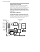
Chapter 1: Introduction VMChannel (not available on CompactPCI and PC/104-Plus) To DB-44 Connector for PCI form factor VID_IN1_1 VID_IN2_1 2:1 MUX VID_IN2_2 VID_IN3_1 Black Lowpass filters/ Gain Aux A/D A/D 24 LUT 3 256x8-bit A/D Sync separator 24 32 24 MJPEG Module Optocoupler Trigger Clk input Clk output Hsync Vsync Trigger Exposure timer1 Exposure timer2 Black Black 4:1 MUX SYNC_IN White White 2:1 MUX VID_IN3_2 To 30-pin male, connector for PC/104-Plus form factor White
Matrox Meteor-II boards 13 dual-tap configurations. It also accepts an external trigger, and can operate in either asynchronous reset mode or next valid frame/field mode. The PCI form factor also includes an auxiliary power supply input, which can be used to draw auxiliary power from your computer to provide power to your camera. Matrox Meteor-II /Digital Matrox Meteor-II /Digital is a digital frame grabber for standard and non-standard video acquisition.
Chapter 1: Introduction Acquisition features Matrox Meteor-II /Digital can acquire digital video from standard and non-standard cameras using the RS-422 or LVDS differential signed format. It supports image acquisition from genlocked cameras in 4 x 8-bit, 2 x 16-bit, or 1 x 32-bit configurations; therefore, up to four cameras can be attached to acquire four 8-bit or component RGB images. The board also supports multi-tap grabs (up to four taps).
Matrox Meteor-II boards 15 The Meteor-II /1394 can also supply power from your computer through the IEEE 1394 interface. Matrox Meteor-II MJPEG module Matrox Meteor-II MJPEG module is an optional board which module supports lossy and lossless MJPEG (interlaced and non-interlaced) compression and decompression of color and monochrome video.
Chapter 1: Introduction Data transfer All versions of the Matrox Meteor-II board allow transfer of live video to Host memory or off-board display memory. To prevent loss of data during long bus-access latencies found in heavily loaded computer systems, the Matrox Meteor-II boards (except Meteor-II /1394) feature 4 Mbytes of SGRAM for temporary frame storage. All boards except Matrox Meteor-II /1394 are also equipped with the Matrox Video Interface ASIC (VIA).
Matrox Meteor-II boards 17 ActiveMIL ActiveMIL is a set of ActiveX controls that are based on MIL. ActiveMIL was designed for rapid application development (RAD) tools, such as Microsoft’s Visual Basic. ActiveMIL is included with MIL. (ActiveMIL-Lite is included with MIL-Lite.) Inspector Inspector is an interactive Windows application for image capture, processing, analysis, and archiving.
Chapter 1: Introduction What you need to get started To begin using Matrox Meteor-II, you need the following: Other useful considerations ■ computer with a PCI bus and a Pentium processor or better. ■ Windows: See your software package for supported environments and RAM requirements. ■ A computer with a relatively up-to-date PCI chipset, such as the Intel 430HX, 430VX, 430TX, 440FX, 440LX, or 440BX for full Matrox Meteor-II functionality.
Inspecting the Matrox Meteor-II package 19 Inspecting the Matrox Meteor-II package Standard package When you unpack your Matrox Meteor-II package, you should check its contents. Note that optional parts might or might not be included, depending on what you ordered. If something is missing or damaged, contact your Matrox representative.
Chapter 1: Introduction ■ DBHD44-TO-13BNC input cable with a high density 44-pin connector and thirteen BNC connectors for the Matrox Meteor-II /Standard (PCI and CompactPCI form factors). Six BNC-TO-SVHS (Y/C) adapter cables are shipped with the DBHD44-TO-13BNC cable. ■ DH44-TO-13BNC/O input cable with a high density 44-pin connector, available for the Matrox Meteor-II /Standard.
Installation overview 21 Installation overview The installation procedure consists of the following steps: 1. Complete the hardware installation as described in Chapter 2. If you have any problems, refer to Appendix A. 2. Complete the software installation as described in Chapter 3. More information For information on using multiple Matrox Meteor-II boards, refer to Chapter 4, and for in-depth hardware information, refer to Chapter 5.
Chapter 1: Introduction Need help? Appendix A offers solutions to potential problems. If your Matrox Meteor-II installation questions are not answered in this manual, contact your local Matrox representative, Matrox Sales Office, or Matrox Imaging Customer Support Group (see the Customer Support section at the back of this manual for telephone numbers).
Chapter 2: Hardware installation This chapter explains how to install the Matrox Meteor-II hardware.
Chapter 2: Hardware installation Installing Matrox Meteor-II Before you install your board, some precautionary measures must be taken. Turn off power to the computer and its peripherals, and drain static electricity from your body (by touching a metal part of the computer chassis). Next, follow the steps to install your board according to its form factor: PCI, CompactPCI, or PC/104-Plus.
Installing Matrox Meteor-II ▲ Caution 25 Some computers have a large, black-ridged heat sink that prevents boards from using most PCI board slots. Your Matrox Meteor-II must not touch this heat sink. Therefore, choose a slot where the board completely avoids it. 3. Connect the Matrox Meteor-II MJPEG module to the board if required. See the section, Installing the Matrox Meteor-II MJPEG module. 4. If present, remove the blank metal plate located at the back of the selected slot.
Chapter 2: Hardware installation ■ If present, remove the blank metal plate located at the back of a slot next to the Matrox Meteor-II /Digital board; do not discard this screw. ■ Install the bracket with the trigger and RS-232 input connectors and fasten it with the screw you just removed. ■ Connect the cables to the 4-pin trigger connector and the 10-pin RS-232 connector on the Matrox Meteor-II /Digital board (see figure below). 9. Replace the cover of your computer. 10.
Installing Matrox Meteor-II 27 Installing Matrox Meteor-II for CompactPCI Use the following steps to install your Matrox Meteor-II board for CompactPCI (3U). Note that a 6U replacement bracket is available. 1. Remove a plate on the subrack, exposing an empty slot. 2. Connect the Matrox Meteor-II MJPEG module to the board if required. See the section, Installing the Matrox Meteor-II MJPEG module. 3.
Chapter 2: Hardware installation Back plate of subrack CompactPCI connector Screw Guide Handle 4. Press the board firmly but carefully into the connector. 5. When the board is in place, the handle opens automatically, exposing a screw. Tighten both this screw, and the one at the top of the bracket. 6. Connect your video sources. For details, see the Connecting external devices section. 7. Turn on your computer.
Installing Matrox Meteor-II 29 Installing Matrox Meteor-II for PC/104-Plus Use the following steps to install your Matrox Meteor-II board for PC/104-Plus: 1. Matrox Meteor-II for PC/104-Plus can operate in either a 5V or 3.3V system. In some cases, a hole in the PC/104-Plus (PCI) connector is filled, which prevents another PC/104-Plus module from being stacked on top. To install Matrox Meteor-II for PC/104-Plus in a system with a specific signalling environment, a pin must be removed.
Chapter 2: Hardware installation 3. Check that you have an available PC/104-Plus connector on the motherboard, or verify that your existing stack can support another board. 4. If you have existing PC/104 boards in your computer, remove them and stack them on the PC/104-Plus board. PC/104 boards must be stacked last. 5. Remove the anchoring screws from the stack; do not discard them since you will need them to fasten the Matrox Meteor-II board. 6.
Installing the Matrox Meteor-II MJPEG module 31 10. Turn on your computer. Under Windows 98, when you boot your computer, Windows’ Plug-and-Play system will detect a new PCI card and you will be asked to assign a driver to it. At this point, you should click on Cancel because the driver will be installed during the installation of MIL or one of its derivatives.
Chapter 2: Hardware installation 2. Once the boards are perfectly aligned, press the module firmly but carefully into the connectors. PC/104-Plus form factor On the PC/104-Plus form factor, the expansion connectors are located on the soldered side of the board.
Connecting external devices 33 Connecting external devices All boards and form factors have their own particularities regarding connectors and input devices. In this section, the boards will be discussed in the following order: ■ Matrox Meteor-II /Standard for PCI. ■ Matrox Meteor-II /Standard for CompactPCI. ■ Matrox Meteor-II /Multi-Channel for PCI. ■ Matrox Meteor-II /Standard and /Multi-Channel for PC/104-Plus. ■ Matrox Meteor-II /Digital. ■ Matrox Meteor-II /1394.
Chapter 2: Hardware installation VMChannel Auxiliary power supply input Video input BNC Connector 1 (male) for expansion module Connector 2 (female) for expansion module Connecting a video input to Meteor-II /Standard for PCI or CompactPCI You can connect video sources to Matrox Meteor-II /Standard’s video input connector, using the optional DBHD44-TO-13BNC cable. This cable has thirteen BNC connectors and a 44-pin high-density D-Subminiature plug.
Connecting external devices Wires Signals Expected Input Form factor BROWN (8) VID_IN8 Analog Video Input8 or Y4 PCI LIGHT BLUE (9) VID_IN9 Analog Video Input9 or Y5 PCI ORANGE (10) VID_IN10 Analog Video Input10 or C5 PCI PINK (11) VID_IN11 Analog Video Input11or Y6 PCI Analog Video Input12 or C6 PCI LIGHT GREEN (12) VID_IN12 GRAY (13) OPTOTRIG External trigger input* 35 PCI, CompactPCI *OPTOTRIG- is usually connected to the ground of the trigger source.
Chapter 2: Hardware installation Connecting Matrox Meteor-II /Standard to the auxiliary power supply input To use Matrox Meteor-II /Standard to power your camera: 1. Use the 4-pin power cable to connect the auxiliary power supply connector to the power supply in the computer. 2. Ensure that the jumper is across the appropriate Matrox Meteor-II auxiliary power supply selection pins, for the required voltage (5 V or 12 V). See Appendix B for a diagram. 3.
Connecting external devices ■ 37 Expansion module interface. Used to connect to the optional Matrox Meteor-II MJPEG module (for image compression and decompression). Connector 2 (female) for expansion module CompactPCI connector Video input BNC Connector 1 (male) for expansion module Connecting a video input (CompactPCI) You can connect video sources to Matrox Meteor-II /Standard’s video input connector CompactPCI form factor, using the optional DBHD44-TO-13BNC cable.
Chapter 2: Hardware installation ■ Auxiliary power supply input. Used to route power from your computer through the Matrox Meteor-II board to your camera. ■ Expansion module interface. Used to connect the optional Matrox Meteor-II MJPEG module (for image compression and decompression).
Connecting external devices 39 *OPTOTRIG- is usually connected to the ground of the trigger source. Connecting Matrox Meteor-II /Multi-Channel to other boards The VMChannel interface allows the transfer of data to other Matrox boards. Insert a VMChannel backplane (available with interconnect kits) across the VMChannel interface to connect the boards. Note that when connecting multiple Matrox boards, at least one of the boards you are connecting must be bus-controller capable.
Chapter 2: Hardware installation ■ PC/104 (ISA) connectors. Two interface connectors to send data across the ISA bus. ■ Expansion module interface. Three connectors used to attach to the optional Matrox Meteor-II MJPEG module (for image compression and decompression); located on the soldered side of the board.
Connecting external devices 41 ■ Digital Video input. Used to receive digital video, as well as send and receive synchronization signals. ■ Trigger input. A connector for direct trigger input in TTL or opto-isolated format. ■ RS-232 input connector. Used as a standard RS-232 serial port interface. ■ VMChannel. Used to send data to another Matrox board.
Chapter 2: Hardware installation Matrox Meteor-II /1394 Matrox Meteor-II /1394 has four connectors, which are indicated in the diagram below. Three of these connectors are located on its bracket, and are discussed in detail in Appendix E. Auxiliary power supply input 1394 ports PCI connector ■ 1394 ports. Used to provide bi-directional serial communication and power. Each I/O port features a standard 6 pin connector. See Appendix E for pinouts. ■ Auxiliary power supply input.
Connecting external devices 43 Connecting Matrox Meteor-II /1394 to the auxiliary power supply input To use Matrox Meteor-II /1394 to power your device: 1. Use the 4-pin power cable to connect the auxiliary power supply connector to the power supply in the computer. 2. Connect your camera’s 1394 cable to one of the board’s ports. Note that the total current drawn by all the cameras is limited to 1.5 A.
Chapter 2: Hardware installation
Chapter 3: Installing software This chapter explains how to install the Matrox Meteor-II software.
Chapter 3: Installing software Installing the software To install any Matrox imaging software, place its CD in the appropriate drive; the setup.exe file will run automatically. While installing the software, you will be asked to provide the following information: ■ The drive and directory in which to install the software. ■ The target operating system and compiler. ■ The type of Matrox hardware that is installed in your computer.
Chapter 4: Using multiple Matrox Meteor-II boards This chapter explains how to use multiple Matrox Meteor-II boards.
Chapter 4: Using multiple Matrox Meteor-II boards Using multiple Matrox Meteor-II boards This section describes how to use multiple Matrox Meteor-II boards. When a grab buffer is selected for display, grabbed images are displayed on the VGA, live or pseudo-live, depending on the operating computer and the position of the windows. Note that the PCI bandwidth is limited, and heavy usage can affect the data transfer in computers using multiple boards.
Multiple board installation Installing multiple PC/104-Plus modules 49 You can stack a maximum of four PC/104-Plus modules, shown in the diagram below. Note that if you have PC/104 modules in your computer, they must be placed at the top of the stack. Top screw ISA connectors PCI connector Host board In addition, you must set the rotary switch of each PC/104-Plus module to a unique setting in the stack.
Chapter 4: Using multiple Matrox Meteor-II boards If you are installing an additional Matrox Meteor-II board on Matrox 4Sight, the module already installed has the setting fixed at 0; therefore, the setting of the additional module must be at a setting other than 0 or 4. Grabbing simultaneously from different boards You can simultaneously grab images from cameras attached to different Matrox Meteor-II boards.
Grabbing simultaneously from different boards PCI bandwidth requirements 51 Matrox Meteor-II /Standard, /Multi-Channel, and /Digital have a low susceptibility to PCI bus latency due to 4 Mbytes of SGRAM. In addition, sustained PCI-transfers to memory require the use of a high performance PCI core-logic chipset, such as the Intel 440LX or 440BX.
Chapter 4: Using multiple Matrox Meteor-II boards
Chapter 5: Matrox Meteor-II hardware reference This chapter explains the architecture of the Matrox Meteor-II hardware, as well as the available features and modes.
Chapter 5: Matrox Meteor-II hardware reference Matrox Meteor-II hardware reference This chapter provides information on the architecture, operating modes, and supported features of the Matrox Meteor-II boards. For a summary of the information given in this chapter and detailed specifications of connectors and pinouts, refer to Appendices B, C, D, and E of this manual.
Matrox Meteor-II /Standard grab section Performance The video timing parameters supported by the Matrox Meteor-II /Standard board are as follows: CCIR 601 sampling rates Square pixel sampling rates NTSC PAL NTSC PAL Field rate (Hz) 60 50 60 50 Pixel/line (Pixels) 858 864 780 944 Active pixel/line (Pixels) 720 720 640 768 Active lines/frame (Lines) 480 580 480 580 Pixel rate (MHz) 13.5 13.5 12.27 14.75 27 27 24.54 29.50 15.750 15.625 15.750 15.
Chapter 5: Matrox Meteor-II hardware reference RGB 8:8:8 (24-bit), RGB 5:6:5, YUV 4:2:2, and YUV 4:1:1 output pixel formats. Note that YUV 4:2:2 output pixel formats are grabbed as YUYV. The video decoder on all form factors also features automatic gain control (AGC). However, you can disable this feature (MIL-Lite MdigControl() with M_GRAB_AUTOMATIC_INPUT_GAIN set to M_DISABLE) and adjust the gain manually (MdigControl() with M_GRAB_INPUT_GAIN).
Matrox Meteor-II /Standard grab section 57 Trigger signals connected to the OPTOTRIG- and OPTOTRIG+ input pins, pass through an opto-coupler, a device that protects the board from outside surges; OPTOTRIG- is usually connected to the ground of the trigger source. The voltage difference across OPTOTRIG+ and OPTOTRIG- must be between 4.05 V and 9.16 V for logic high, and between -5.0 V and 0.8 V for logic low. Refer to Appendix B for the pinouts of these signals on your respective form factor.
Chapter 5: Matrox Meteor-II hardware reference Matrox Meteor-II /Multi-Channel grab section The grab section of the Matrox Meteor-II /Multi-Channel board captures monochrome or component-RGB video signals from standard and non-standard cameras. Six monochrome or two RGB cameras can be attached.
Matrox Meteor-II /Multi-Channel grab section Performance 59 The video timing parameters (including those for progressive scan) supported by the Matrox Meteor-II /Multi-Channel board are as follows: Max Number of pixels / line (including sync and blanking) 4096* Number of lines / frame (including sync and blanking) 4096* Sampling rate (with external clock input, or in line-locking mode) 30 MSPS Note that the maximum number of pixels per line that MIL supports is: Pixels -------------- x Number of Lines
Chapter 5: Matrox Meteor-II hardware reference You can change the gain value using the MIL-Lite MdigControl() command. The supported gain factors are as follows: Input video signal amplitude (excluding sync) Total input video Required signal amplitude gain (including sync) setting MIL 0.0 V up to 0.5 V 0.0 - 0.7 Vpp 4 M_GAIN3 0.5 V up to 0.7 V 0.7 - 1.0 Vpp 2.8 (default) M_GAIN2 0.7 V up to 1.0 V 1.0 - 1.4 Vpp 2 M_GAIN1 1.0 V up to 1.5 V 1.4 - 2.1 Vpp 1.3 M_GAIN0 1.5 V up to 2.0 V 2.
Matrox Meteor-II /Multi-Channel grab section 61 ■ The on-board crystal oscillator. ■ The horizontal video synchronization signal supplied by the video source (line-locked mode). When in line-locked mode and accepting a composite video signal, the PLL can synchronize to either serrated or block vertical synchronization signals. ■ The clock signal supplied by the video source (to generate a different clock).
Chapter 5: Matrox Meteor-II hardware reference Trigger Matrox Meteor-II /Multi-Channel accepts an external trigger input which allows image acquisition to be synchronized to external events. The board can operate in one of two modes, and the selected mode is specified by the DCF. Matrox Meteor-II /Multi-Channel can operate in next valid frame/field mode When in this mode, the digitizer waits for the next valid frame or field (as specified by the DCF file) before commencing the grab.
Matrox Meteor-II /Multi-Channel grab section opto-isolated trigger 63 Trigger signals connected to the OPTOTRIG- and OPTOTRIG+ input pins, pass through an opto-coupler, a device that protects the board from outside surges; OPTOTRIG- is usually connected to the ground of the trigger source. The voltage difference across OPTOTRIG+ and OPTOTRIG- must be between 4.05 V and 9.16 V for logic high, and between -5.0 V and 0.8 V for logic low. Refer to Appendix C for the pinouts of these signals on your board.
Chapter 5: Matrox Meteor-II hardware reference Using the auxiliary power supply Matrox Meteor-II /Multi-Channel can supply power to your camera. Use the 4-pin power cable provided with your board to connect to the power supply of your computer. The operating voltage can be set to either 5 V or 12 V, but the current drawn by all cameras is limited to 1.5 A. The circuit uses an auto-resettable fuse.
Matrox Meteor-II /Digital grab section 65 VMChannel 32 Data 100-Pin Connector Clk input Clk output Hsync input Hsync output Vsync input Vsync output Valid frames/line Trigger Exposure timer1 Exposure timer2 Aux 1 input Aux 2 input Aux 1 output Aux 2 output Exposure timer1 Exposure timer2 Camera CTRL1 Camera CTRL2 Camera CTRL3 RS-422/ LVDS* Receiver 32 LUT 4 256x8-bit or 2 4Kx16-bit 32 32 RS-422/ LVDS* Drivers & Receivers TTL Buffers PSG VIA 64 Trigger 9-Pin Female Trigger Connector Trigger
Chapter 5: Matrox Meteor-II hardware reference UART Matrox Meteor-II /Digital features a Universal Asynchronous Receiver/Transmitter (UART) that provides an RS-232 serial interface. For example, this allows remote camera configuration, a motion control unit, or of a program logic controller (PLC). The UART is programmed using the MIL-Lite function, MdigControl() with the M_UART... control types. Lookup table (LUT) The Matrox Meteor-II /Digital board has four 256x8-bit programmable lookup tables.
Matrox Meteor-II /Digital grab section 67 Auxiliary Seven general purpose auxiliary signals are supported: four RS-422 or LVDS user signals (two input, two output), and three TTL output signals. These are available for controlling external devices, such as a strobe light. User signals are programmed using the MIL-Lite command MdigControl(). Exposure Two timers in the PSG can generate two exposure signals simultaneously. There are available in TTL or RS-422/LVDS formats.
Chapter 5: Matrox Meteor-II hardware reference Matrox Meteor-II /1394 Matrox Meteor-II /1394 is capable of acting as bus manager (cycle master), isochronous resource manager, and node controller ("root"). The cycle master triggers the data signal at 125-microsecond intervals. The isochronous resource manager is responsible for reserving, distributing, and managing the two modes of data streams (isochronous and asynchronous) along the available bandwidth.
Matrox Meteor-II /1394 69 Physical Layer The physical layer (PHY) is part of a bi-directional interface between the link layer (Link) and the actual IEEE 1394 serial bus. The physical layer acts as a converter, reformatting the commands and digital data it receives, so that the data can be transmitted over the serial bus. The PHY monitors the line conditions to determining connection status, for initialization and arbitration, and for packet reception and transmission.
Chapter 5: Matrox Meteor-II hardware reference Data interfaces Video Interface ASIC With the exception of Meteor-II /1394, all Meteor-II boards have a VIA, which acts mainly as a bridge to the PCI bus. The VIA is capable of high-speed image transfers to Host memory or other PCI devices across the PCI bus. It uses 4 Mbytes of SGRAM (on-board memory) to store data until the PCI bus becomes available.
Matrox Meteor-II MJPEG Module 71 VMChannel Matrox Meteor-II provides a 32-bit non-bus controller VMChannel interface for a secondary or additional high-speed connection between on-board and external devices. On a 68-wire ribbon cable system, the VMChannel runs at 25 MHz for 100 Mbytes/sec peak transfer rates. On a backplane system, it runs at 33 MHz for 132 Mbytes/sec peak transfer rates. The VMChannel is only available on the PCI form factor of Matrox Meteor-II/Standard, /Multi-Channel, and /Digital.
Chapter 5: Matrox Meteor-II hardware reference Pixel Data Input/Output Meteor-II Grab Port Interface Color Space Converter SRAM (64Kbytes) 16 Strip Buffer Memory 24 Block Data Host Interface 8 24 8 Host Interface Pixel Interface 8 Host Interface JPEG Processor Progressive Path MJPEG FPGA Code Interface 8 MJPEG Module JPEG Processor Interface Memory Port 64 VIA SGRAM Interface Port The Matrox Meteor-II MJPEG module supports lossy compression of RGB 8:8:8 and YUV 4:2:2 standard vi
Matrox Meteor-II MJPEG Module 73 JPEG Processor During compression, the JPEG Processor receives the 8 x 8 pixel blocks and compresses them according the JPEG standard. Both lossy and lossless formats are supported. During decompression, the JPEG Processor decompresses the data, and transfers the 8 x 8 pixel blocks to the Color Space Converter. MJPEG FPGA The MJPEG FPGA controls the direction of compressed and decompressed data and generates control signals on the module.
Chapter 5: Matrox Meteor-II hardware reference Decoding During decompression, the data enters through the memory port on the MJPEG FPGA chip, and passes through the JPEG processor, the Color Space Converter, and finally exits through the Matrox Meteor-II grab port. Host ❖ Due to a hardware limitation, the MJPEG module on the Matrox Meteor-II /Standard cannot decompress JPEG (non-interlaced) compressed data; decompression of JPEG data will be performed by the Host.
Appendix A: Troubleshooting This appendix gives suggestions to help you resolve potential problems. If your problem is not addressed here, contact your local Matrox representative, Matrox Sales Office, or the Matrox Imaging Customer Support Group.
Appendix A: Troubleshooting Troubleshooting If you have problems using your Matrox Meteor-II board, please try the following: ■ Check for disconnected power cords. ■ Read the Common problems and solutions section in this chapter. If your problem is not addressed in this chapter or if the solutions suggested don’t work for you, contact your local Matrox representative, Matrox Sales Office, or the Matrox Imaging Customer Support Group.
Common problems and solutions 77 If the Startup column reads Automatic, and the Status column is blank, the driver can be started by clicking the Start button. ❐ When the board fails to start under Windows 98, the driver is probably not installed. Check for a Meteor-II device in the Windows Device Manager property sheet. This sheet can be accessed using the System utility in the Control Panel. If you do not see a Meteor-II device under Matrox Imaging Adapters, you will have to reinstall the driver.
Appendix A: Troubleshooting If the above solution does not work, try the following to determine if there is an IRQ conflict. ☛ ❐ Under Windows NT, go to Windows NT Diagnostics property sheet (found under Start Programs Administrative Tools (Common). Under the Resources tab, check for devices that are sharing an IRQ with your Matrox frame grabber. ❐ Under Windows 98, right-click on My Computer, and select Computer from the presented menu.
Common problems and solutions ☛ 79 IRQ conflicts In general, PCI devices can share an interrupt line (IRQ). However, sometimes this might not be possible; for example, complex PCI devices, or bus master devices should not share an IRQ. The types of difficulties that you might run into are as follows: ■ IRQ conflict under Windows NT 4.
Appendix A: Troubleshooting ■ Under Windows NT, go to Windows NT Diagnostics property sheet (found under Start Programs Administrative Tools (Common). Under the Resources tab, check for devices that are sharing an IRQ with your Matrox frame grabber. ■ Under Windows 98, right-click on My Computer, and select Computer from the presented menu. Go to View Resources, selecting the Interrupt request (IRQ) checkbox. Check for devices that are sharing an IRQ with your Matrox frame grabber.
Appendix B: Technical information Matrox Meteor-II /Standard This appendix contains information that might be useful when installing your Matrox Meteor-II /Standard board.
Appendix B: Technical information Matrox Meteor-II /Standard Technical information This appendix contains information that might be useful when installing your Matrox Meteor-II /Standard board. General information ■ Operating system: See your software manual for supported versions of Windows. ■ System requirements: A computer with a PCI bus and a Pentium processor or equivalent. Some older systems use a core logic chipset (interfaces PCI with Host memory) that has limited throughput capabilities.
Board input and output connectors ❐ Features an RS-232 port. ❐ Features 32-bit bus-controller VMChannel interface. 83 Board input and output connectors PCI form factor Matrox Meteor-II /Standard PCI form factor has six interface connectors: a VMChannel, an auxiliary power supply input, a video input, two connectors1 for an expansion module, and a BNC connector.
Appendix B: Technical information Matrox Meteor-II /Standard CompactPCI form factor Matrox Meteor-II /Standard CompactPCI form factor has five interface connectors: a video input, a BNC, two connectors for an expansion module, and a CompactPCI connector.
Board input and output connectors 85 Video input connector on Matrox Meteor-II for PCI and CompactPCI pin 30 pin 44 pin 16 pin 31 pin 15 pin 1 The video input connector is a high density DB-44 female connector on the PCI and CompactPCI form factors. Its pinout is shown below. Note the Form Factor column specifies the board which supports that particular pinout. Pin Signal I/O Description Form Factor 1 DC_OUT O +12 V/ +5 V Power Supply.
Appendix B: Technical information Matrox Meteor-II /Standard Pin Signal I/O Description Form Factor 20 VID_IN9 I Analog Video Input #9 or Y5 PCI 21 RTS O Request To Send (RS-232). PCI, CompactPCI 22 RX I Receive (RS-232). PCI, CompactPCI 23 VID_IN8 I Analog Video Input #8 or Y4 PCI 24 USER(1)_OUT O Auxiliary User Output #1 PCI, CompactPCI 25-31 GND - Ground.
Board input and output connectors 1 2 87 29 Video input connector on Matrox Meteor-II /Standard for PC/104-Plus 30 The video input connector on the Meteor-II /Standard for PC/104-Plus is located on the top side of the board.
Appendix B: Technical information Matrox Meteor-II /Standard The mating connector included with the board is a 30-pin male, 0.050 pitch right angle connector. Parts for cables can be purchased from: ■ ■ Manufacturer: Connector Fujitsu FCN-217J030-G/O This connector interfaces with a ribbon cable, 0.025 inch pitch (0.635 mm), AWG #30 (solid wire).
Board input and output connectors Pin Signal Pin Signal 2 N/C* 36 DGND 3 BSN[0] 37 BSN[1] 4 DGND 38 SNRDYN 5 CONTROL 39 DGND 6 N/C 40 DGND 7 CLK 41 DGND 8 VMSENSE 42 DGND 9 MASK0 43 MASK1 10 DGND 44 DATA[0] 11 DATA[1] 45 DGND 12 DATA[2] 46 DATA[3] 13 DGND 47 DATA[4] 14 DATA[5] 48 DGND 15 DATA[6] 49 DATA[7] 16 DGND 50 DATA[8] 17 DATA[9] 51 DGND 18 DATA[10] 52 DATA[11] 19 DGND 53 DATA[12] 20 DATA[13] 54 DGND 21 DATA[14] 55 DAT
Appendix B: Technical information Matrox Meteor-II /Standard Pin Signal Pin Signal 27 DATA[22] 61 DATA[23] 28 DGND 62 DATA[24] 29 DATA[25] 63 DGND 30 DATA[26] 64 DATA[27] 31 DGND 65 DATA[28] 32 DATA[29] 66 DGND 33 DATA[30] 67 DATA[31] 34 DGND 68 SBN * N/C = Not connected. This means that the pin might be defined as part of the VMChannel interface standard but it is not used on the Matrox Meteor-II /Standard board.
Board input and output connectors 91 The pinout of the auxiliary power supply input connector is as follows: Pin Description 1 +12 V 2 Ground 3 Ground 4 +5 V For customers building their own cable, the part number of the camera supply connector is as follows: ■ ■ Manufacturer: Connector: VEN 2490-04PRT Auxiliary power supply selection The following diagram shows the location of the auxiliary power supply selection and their corresponding pin numbers: +5V +12V pin 1 pin 2 pin 3
Appendix B: Technical information Matrox Meteor-II /Standard As shown in the table below, place the jumper across pins 1 and 2 for a +5 V supply output and across pins 2 and 3 for a +12 V supply output. Jumper 1 pin 2 pin 3 pin Pin Description 1-2 +5 V (default) 2-3 +12 V Side view By default, auxiliary power supply is strapped for +5 V (pins 1-2). Specifications Electrical Form Factor Operating Voltage and current Power Consumptiona 5 V ±5% -5 V ±5% 3.
Appendix C: Technical information Matrox Meteor-II /Multi-Channel This appendix contains information that might be useful when installing your Matrox Meteor-II /Multi-Channel board.
Appendix C: Technical information Matrox Meteor-II /Multi-Channel Technical information This appendix contains information that might be useful when installing your Matrox Meteor-II /Multi-Channel board. Global information ■ Operating system: See your software manual for supported versions of Windows. ■ System requirements: A computer with a PCI bus and a Pentium processor or equivalent.
Board input and output connectors 95 ❐ Features strap-selectable 5 or 12 V DC output (PCI form factor only). ❐ Features 32-bit bus-controller VM Channel interface. Board input and output connectors The Matrox Meteor-II /Multi-Channel PCI form factor has six interface connectors: a VMChannel, an auxiliary power supply input, a video input, two connectors for an expansion module.
Appendix C: Technical information Matrox Meteor-II /Multi-Channel PC/104-Plus form factor Matrox Meteor-II for the PC/104-Plus form factor (stand alone version) has five interface connectors: video input, two connectors for the expansion module, a PC/104-Plus (PCI) connector, and PC/104 (ISA) connector.
Board input and output connectors Pin Signal Description 2 HSYNC_TTL Hsync input or output (TTL). 38 EXP(1) Exposure #1 output (TTL). 23 EXP(2) Exposure #2 output (TTL). 36 TX Transmit (RS-232). 22 RX Receive (RS-232). 6 CTS CTS (RS-232). 21 RTS RTS (RS-232). 39 USER1IN+ Auxiliary User Input #1 (positive). 12 USER1IN- Auxiliary User Input #1 (negative). 9 USER2IN+ Auxiliary User Input #2 (positive). 10 USER2IN- Auxiliary User Input #2 (negative).
Appendix C: Technical information Matrox Meteor-II /Multi-Channel Video input connector on the Meteor-II /Multi-Channel for PC/104-Plus 1 29 2 30 The video input connector on the Meteor-II /Multi-Channel for PC/104-Plus is located on the top side of the board. Its pinout is as follows: Pin Signal I/O Description 2 VID1_IN1 I RED Analog Video Input (Channel 1). 4 VID1_IN2 I GREEN Analog Video Input (Channel 1). 6 VID1_IN3 I BLUE Analog Video Input (Channel 1).
Board input and output connectors Pin Signal 1, 3, 5, 7, GND 9, 11, 13, 21, 25, 27 99 I/O Description Ground. The connector used is a 30-pin male, 0.050 pitch right angle connector. For customers planning to build their own cables, parts can be purchased from: ■ ■ Manufacturer: Connector Fujitsu FCN-217J030-G/O This connector interfaces with a ribbon cable, 0.025 inch pitch (0.635 mm), AWG #30 (solid wire).
Appendix C: Technical information Matrox Meteor-II /Multi-Channel Specifications Electrical Form Factor Operating Voltage and current Power Consumptiona 5 V ±5% -5 V ±5% 3.3 V ±5% 12 V ±10% -12 V ±10% PCI 1.0 A n/a PC/104-Plus 140 mA 60 mA n/a 150 mA 75 mA 7.7 W 1.03 A 15 mA n/a 5.08 W a. This number represents the total power consumption of the Matrox Meteor-II board only.
Appendix D: Technical information Matrox Meteor-II /Digital This appendix contains information that might be useful when installing your Matrox Meteor-II /Digital board.
Appendix D: Technical information Matrox Meteor-II /Digital Technical information This appendix contains information that might be useful when installing your Matrox Meteor-II /Digital board. Global information ■ Operating system: See your software manual for supported versions of Windows1. ■ System requirements: A computer with a PCI bus and a Pentium processor or equivalent. Some older systems use a core logic chipset (interfaces PCI with Host memory) that has limited throughput capabilities.
Board input and output connectors ❐ Features 4 Mbytes of SGRAM. ❐ Features 32-bit bus-controller VM Channel interface. Board input and output connectors Matrox Meteor-II digital has four user connectors: a VMChannel, a trigger input, a RS-232 input, and a digital interface.
Appendix D: Technical information Matrox Meteor-II /Digital Digital interface connector The digital interface connector has 100 pins.
Board input and output connectors PIN SIGNAL 105 PIN SIGNAL 29 DATA, INPUT, 14+ 79 DATA, INPUT, 30+ 30 DATA, INPUT, 14- 80 DATA, INPUT, 30- 31 DATA, INPUT, 15+ 81 DATA, INPUT, 31+ 32 DATA, INPUT, 15- 82 DATA, INPUT, 31- 33 HSYNC, INPUT, + 83 HSYNC, OUTPUT, + 34 HSYNC, INPUT, - 84 HSYNC, OUTPUT, - 35 VSYNC, INPUT, + 85 VSYNC, OUTPUT, + 36 VSYNC, INPUT, - 86 VSYNC, OUTPUT, - 37 GROUND 87 EXPOSURE1, OUTPUT, TTL 38 GROUND 88 EXPOSURE2, OUTPUT, TTL 39 CLOCK, INPUT, +
Appendix D: Technical information Matrox Meteor-II /Digital RS-232 input connector The RS-232 signals are routed through a 9-pin male connector on the second mounting bracket, to a 10-pin RS-232 connector on the board (see the installation diagram in Chapter 2). The pinouts of the 9-pin DB9 male connector are as follows: Pin 1 2 3 4 5 Signal Description 1 N/C Not connected. 2 RX Receive. 6 3 TX Transmit. 7 8 9 4 N/C Not connected. 5 GND Ground. 6 N/C Not connected.
Board input and output connectors 107 VMChannel interface connector The VMChannel interface allows Matrox Meteor-II to share data with any Matrox imaging board that has a VMChannel interface capable of performing the bus controller function. A VMChannel backplane (available with the GEN-BUS/... interconnect kits) must be inserted across the VMChannel interfaces of the boards. For pinout information, see VMChannel interface connector in Appendix B.
Appendix D: Technical information Matrox Meteor-II /Digital By default, all jumpers are in place. If more than one load (for example, two line-locked cameras) are to be connected to the TRIG, VSYNC, HSYNC, or CLKIN, the corresponding jumpers should be removed. Specifications Electrical Operating voltage and current: ■ 5 V ±5%, 1.4 A ■ 12 V ±10%, 30 mA Power consumption: ■ 7.36 watts Environmental ■ Min./max. ambient operating temperature: 0°C - 55° C. ■ Min./max.
Appendix E: Technical information Matrox Meteor-II /1394 This appendix contains information that might be useful when installing your Matrox Meteor-II /1394 board.
Appendix E: Technical information Matrox Meteor-II /1394 Technical information This appendix contains information that might be useful when installing your Matrox Meteor-II /1394. Global information ■ Operating systems: See your software manual for supported versions of Windows. ■ System requirements: A computer with a PCI bus and a Pentium processor or equivalent. Some older systems use a core logic chipset (interfaces PCI with Host memory) that has limited throughput capabilities.
Board input and output connectors 111 Board input and output connectors Matrox Meteor-II /1394 has four interface connectors: three 1394 ports and an auxiliary power supply input: Auxiliary power supply input 1394 ports PCI connector IEEE 1394 ports Each IEEE 1394 port is a 6-pin connector. Its pinout is as follows: Pin Signal 1 +12 V, 1.
Appendix E: Technical information Matrox Meteor-II /1394 Auxiliary power supply input 1 2 3 4 The auxiliary power supply input is a standard 4-pin male connector. Use the cable provided with your board to connect to the power supply of your computer.
Specifications 113 Specifications Electrical Operating voltage and current: ■ 5 V ±5%, 250 mA ■ 12 V ±10%, 50 mA Power consumption: ■ 7.36 watts1 Environmental ■ Min./max. ambient operating temperature: 0°C - 55° C. ■ Min./max. storage temperature: -40° C - 75° C. ■ Max. altitude for operation: 3000 meters. ■ Max. altitude for transport: 12000 meters. ■ Operating humidity: 20 - 80% relative humidity (non-condensing) 1.
Appendix E: Technical information Matrox Meteor-II /1394
Appendix F: Listing of Matrox Meteor-II Boards This appendix lists specific versions and revisions of Matrox Meteor-II boards, including the MJPEG module.
Appendix F: Listing of Matrox Meteor-II Boards Matrox Meteor-II boards Board Version Description PCI form factor Matrox Meteor-II 750-00 rev. A /Standard PCI Original version. 750-01 rev. A No functional change. 750-02 rev. A Added expansion connectors, moved up from 4 to 7 inputs. 750-02 rev. B No functional change. 750-0201 rev. A Support for KS0127 rev. B video decoder, and moved up from 7 to 12 inputs. Matrox Meteor-II 807-00 rev. A /Standard CompactPCI 807-00 rev. B 807-0001 rev.
Matrox Meteor-II boards Board Version Matrox Meteor-II 886-00 rev. A /Multi-Channel PC/104-Plus 886-00 rev. B 886-01 rev. A 117 Description Original version. No functional change. Replaced expansion connectors (for 896-01). Matrox Meteor-II MJPEG Module PCI and CompactPCI PC/104-Plus 774-00 rev. A Original version. Interlaced compression only. 774-01 rev. A No functional change. 774-01 rev. B No functional change. 913-00 rev. A Supports interlaced and non-interlaced compression.
Appendix F: Listing of Matrox Meteor-II Boards
Appendix G: Glossary This appendix defines some of the specialized terms used in this Matrox Meteor-II document.
Appendix G: Glossary ■ ASIC Application-specific integrated circuit. An integrated circuit custom-made to meet the requirements of a specific application. It integrates several digital and/or analog functions into a single die. This results in a reduction in cost, board area, and power consumption, while improving performance when compared to an equivalent implementation using off-the-shelf components. ■ Backplane A circuit board that acts as a pathway between multiple boards.
■ Color space A color space is a way of representing and describing the complete range of perceived colors. A number of color spaces have been developed. Common color spaces are RGB and HSL. Both describe the same range of perceivable colors. ■ Composite sync A synchronization signal made up of two components: one horizontal and one vertical. ■ Contiguous memory A block of memory occupying a single, consecutive series of locations. ■ DCF Digitizer Configuration Format.
Appendix G: Glossary ■ Frame A single image grabbed from a video camera. ■ Frame buffer A frame buffer is a dedicated storage area often used for data transfers between devices of differing speeds. For example, since a computer sends out data faster than a screen can display it, the data is temporarily stored in the frame buffer. The buffer is generally thought of as a two-dimensional surface with a certain pixel depth. ■ Grab To acquire an image from a camera.
■ Live processing See real-time processing. ■ LUT mapping Look-up table mapping. A point-to-point operation that uses a table to define a replacement value for each possible pixel value in an image. ■ LVDS Low-Voltage Differential Signaling. It is a way to communicate data using a very low voltage swing (about 350mV) over two differential printed circuit board (PCB) traces or a balanced cable. ■ MSPS Mega Samples per second. ■ PCI Peripheral Component Interconnect.
Appendix G: Glossary ■ Real-time processing The processing of an image as quickly as the next image is grabbed. Also known as live processing. ■ Reference levels The zero and full-scale levels of an analog-to-digital converter. Voltages below a black reference level are converted to a zero pixel value; voltages above a white reference level are converted to the maximum pixel value. Together with the analog gain factor, the reference levels affect the brightness and contrast of the resulting image.
■ VIA Video Interface ASIC. A custom ASIC that connects all the data buses on the board (the grab, VMChannel, and PCI bus) to one another, and directs and monitors data flow "traffic". It is a video interface that provides various ways of inputting and outputting data. ■ VMChannel Vesa Media Channel. An industry standard 32-bit bus designed for carrying video data. On Matrox Meteor-II, it is used primarily to share data with other Matrox imaging boards.
Appendix G: Glossary
Index A acquisition features /1394 68 /Digital 64 /Multi-Channel 58 /Standard 54 automatic gain control /Multi-Channel 59 /Standard 56 auxiliary power supply /1394 43, 112 /Multi-Channel 39, 64, 99 /Standard 36, 57, 90–92 D data interfaces PCI interface 70 VIA 70 VMChannel 71 VMChannelconnectors VMChannel 71 data transfer 16 DMA memory 77 E environmental specifications /1394 113 /Digital 108 /Multi-Channel 100 /Standard 92 C G cameras genlocked 50 grabbing images 50 multi-tap 70 number of cameras per b
H hardware connecting external devices 33 PCI slot 18, 77 reference 54 heat sink 25, 48 MJPEG decompression 74 mode master 61 slave 61 multiple Matrox Meteor-II boards grabbing 50 PCI bandwidth 48, 51 multi-tap cameras 70 I installation CompactPCI form factor 27 MJPEG module PC/104-Plus 32 PCI and CompactPCI 31 multiple boards PC/104-Plus 49 PCI and Compact PCI 48 overview 21 PC/104-Plus form factor 29 PCI form factor 24 software 46 IRQ conflicts 79 J Jumpers /Digital 107 L low-pass filter /Multi-Channe
S SGRAM Matrox Meteor-II boards 16 slave mode 61 specifications electrical /1394 113 /Digital 108 /Multi-Channel 100 /Standard 92 environmental /1394 113 /Digital 108, 113 /Multi-Channel 100 /Standard 92 technical /Digital 102, 110 /Multi-Channel 94 /Standard 82 synchronization 61 T technical information /1394 110 /Digital 102 /Multi-Channel 94 /Standard 82 timing field rate /Standard 55 line rate /Standard 55 lines/frame /Digital 65 /Multi-Channel 59 /Standard 55 pixel rate /Standard 55 pixels/line /Digit
Customer support Note: The most up-to-date telephone numbers are available from the Matrox internet web site. If you have a question that is not answered in your manual, in the release notes, or in the readme files on the software CDs, contact your local representative, your regional Matrox office (if applicable), or Matrox Canada (corporate headquarters). To ensure that Customer Support can answer your questions quickly, fill out and fax the "Product Assistance Request" form before calling.
Warranty This product is warranted against defects in materials and workmanship for a period of one year from date of delivery. We will repair or replace products that prove to be defective during the warranty period provided they are returned, at the user’s expense, to Matrox Electronic Systems Limited. No other warranty is expressed or implied. Matrox is not liable for consequential damages. If you wish to return your board, contact the Matrox authorized dealer where you purchased the board for service.
Product Assistance Request Form Name: Company: Address: Phone: E-mail: Hardware Specific Information Computer: System memory: System BIOS rev: Video card used: Network Card: Other cards in system: Software Specific Information Operating system: Matrox SW used: Compiler: Fax: CPU: PCI Chipset: Resolution: Network Software: Rev: Rev: Rev: Fill out only if you are returning a board RMA #: Who were you talking to in customer support? Date board was received: Date of failure: MOD #: SER #: REV #: PMB #: PNS
Describe the problem:
Regulatory Compliance FCC Compliance Statement Warning Changes or modifications to this unit not expressly approved by the party responsible for the compliance could void the user’s authority to operate this equipment. Note This device complies with Part 15 of FCC Rules. Operation is subject to the following two conditions: 1. this device may not cause harmful interference, and 2. this device must accept any interference received, including interference that may cause undesired operation.
EC Declaration of Conformity WARNING: This is a class A product. In a domestic environment this product may cause radio interference in which case the user may be required to take adequate measures AVERTISSEMENT: Cet appareil est de la classe A. Lorsque cet appareil est utilisé dans un environnment résidentiel, il peut entraîner des interférences radioélectriques. Dans ce cas, l'usager peut être prié de prendre des mesures correctives appropriées.