
Laptop User Manual

9-2
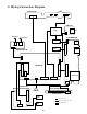
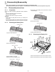
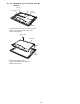
3. Remove the 12 Screws <N6>.
4. Remove the Cable Hold Sheet while opening the Rear
Cabinet ASS'Y slowly.
5. Remove the Cable hooked on the Lamp Cable Spring.
6. Remove both the Inverter and the Inverter Case.
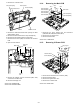
7. Remove the Connector (CN6) connected to the IO Power
PCB.
8. Open the Rear Cabinet.
9. Remove the Clamper and the Connectors (CN2, CN6)
connected to the Main PCB.
10. Remove the Display Unit.
Screws <N4>:DXSB2+6FNL
Screws <N6>:DXYN26+J6FNL
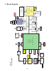
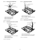
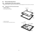
9.1.4. Removing the Main PCB
1. Disconnect the seven Cables from the Connectors
(CN3,CN4,CN7,CN9,CN10,CN12,CN13).
2. Remove the four Screws <N1>.
3. Remove the Main PCB.
Screws <N1>: XSB2+4FNL
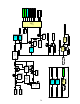
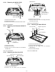
9.1.5. Removing IO Power PCB
1. Disconnect the Cable from the Connector (CN8).
2. Remove the Edge Sheet.
3. Remove the eight Screws <N1>.
4. Remove the IO Power PCB.
Screws <N1>:XSB2+4FNL
Lamp Cable Spring
Cable Holder Sheet
Rear Cabinet
IO Power P.C.B.
Inverter
Connector(CN6)
Cable
Display
Unit
Connector
(CN2)
Connector
(CN6)
Main P.C.B.
Clamper
<N1>
<N1>
<N1>
<N1>
Connector(CN7)
Connector(CN3)
Connector(CN13)
Connector(CN4)
Connector(CN9)
Main P.C.B.
Connector(CN12)
Connector(CN10)
Connector(CN8)
IO Power P.C.B.
Edge Sheet
<N1>
<N1>
<N1>
<N1>
<N1>
<N1>
<N1>
<N1>