ORDER NO. CPD0711208C1 Notebook Computer Model No. CF-19FHGAXxM This is the Service Manual for the following areas. M …for U.S.A. and Canada Model No. CF-19FHGAX 1 M 1: Operation System A: Microsoft® Windows® XP Professional J: Microsoft® Windows® VISTA Business © 2007 Matsushita Electric Industrial Co., Ltd. All rights reserved. Unauthorized copying and distribution is a violation of law.
WARNING For U.K. This apparatus must be earthed for your safety. To ensure safe operation the three-pin plug must be inserted only into a standard three-pin power point which is effectively earthed through the normal household wiring. Extension cords used with the equipment must be three-core and be correctly wired to provide connection to earth. Wrongly wired extension cords are a major cause of fatalities.
LASER SAFETY INFORMATION For U.S.A . Class 1 LASER-Product This product is certified to comply with DHHS Rules 21 CFR Subchapter J. This product complies with European Standard EN60825 (or IEC Publication 825) For all areas This equipment is classified as a class 1 level LASER product and there is no hazardous LASER radiation. Caution: (1) Use of controls or adjustments or performance of procedures other than those specified herein may result in hazardous radiation exposure.
SAFETY PRECAUTIONS 1. Before servicing, unplug the power cord to prevent an electric shock. 2. When replacing parts, use only manufacture's recommended components for safety. 3. Check the condition of the power cord. Replace if wear or damage is evident. 4. After servicing, be sure to restore the lead dress, insulation barriers, insulation papers, shields, etc.
Avoid Extreme Heat (Near the Fire, in Direct Sunlight, for Example) Electrolyte leakage, generation of heat, ignition or rupture may result. Do Not Insert Sharp Objects into the Battery Pack, Expose It to Bumps or Shocks, Disassemble, or Modify It Electrolyte leakage, generation of heat, ignition or rupture may result. Do Not Short the Positive (+) and Negative (-) Contacts Generation of heat, ignition or rupture may result.
CONTENTS 1. Specifications 1-1 2. Names and Functions of Parts 2-1 3. Block Diagram 3-1 4. Diagnosis Procedure 4-1 5. Power-On Self Test (Boot Check) 5-1 6. List of Error Codes 6-1 7. Self Diagnosis Test 7-1 8. Wiring Connection Diagram 8-1 9. Disassembly/Reassembly 9-1 10. Exploded View 10-1 11.
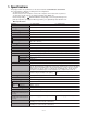
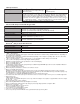
1. Specifications This page provides the specifications for the basic model CF-19FHGAXBM/CF-19FDGAXVM. The model number is different according to the unit configuration. To check the model number: Check the bottom of the computer or the box the computer came in at the time of purchase. To check CPU speed, memory size and the hard disk drive (HDD) size: Reference Manual “Setup Utility”) and select [Information] menu.
Main Specifications Operating System Microsoft® Windows® XP Professional Service Microsoft® Windows® XP Tablet PC Edition Pack 2 with Advanced Security Technologies 2005 (NTFS File System) (NTFS File System) Utility Programs DMI Viewer, Microsoft® Windows® Media Player 10, Adobe Reader, PC Information Viewer, SD Utility, Icon Enlarger, Loupe Utility, Intel® Matrix Storage Manager, Intel® PROSet/Wireless Software*7, Bluetooth™ Stack for Windows® by TOSHIBA*8 , Wireless Switch Utility, Hotkey Settings, Bat
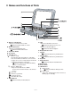
2. Names and Functions of Parts A: Wireless LAN Antenna Reference Manual “Wireless LAN” B: Bluetooth Antenna Reference Manual “Bluetooth” C: Stylus/Pen Holder D: Touch Pad E: LED Indicator : Wireless ready This indicator lights when Wireless LAN, Bluetooth, and/or Wireless WAN are connected and ready. It does not necessarily indicate the On/Off condition of the wireless connection.
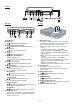
Left side Rear side Bottom A: DC-IN Jack B: USB Port Reference Manual “USB Devices” C: IEEE 1394 Interface Connector Reference Manual “IEEE 1394 Devices” L: Microphone Jack A condenser microphone can be used. If other types of microphones are used, audio input may not be possible, or malfunctions may occur as a result.
/ 90 Print Finger USB 2.0 PortRep USB 2.0 x2 CRT RF Board antenna 2.0 Bluetooth USB Digitizer HSDPA, EVDO USB (1.5Gb/s) SATA 8M SPI BIOS CRT SW antenna Screen Touch USB antenna GPS LPC Bridge USB 2.0 INTEL 1.5V Interface DMI Bridge Serial 3 PortRep Serial2 USB Bridge PCI-E Bridge PCI INTEL (1.05 ) 1.05V Serial1 Buffer SMSC SIO10N268 Super I/O PCI-Express AC Link 64bit BUS 1.8V 533MHz 64bit BUS 1.
4 Diagnosis Procedure 4.1.
4.2. Troubleshooting Please take note of the following two points with regard to troubleshooting: 1. Know-how of diagnosis upon occurrence of heavy troubles, e.g. Set cannot be turned ON , Set fails to start , No display on screen , etc. 2. Explanation of each trouble, mainly symptom of trouble in operation. Flow Chart START START Set cannot be supplied with current. Power lamp fails to light up. Pay attention to the following points when in pursuit of the cause of a troubleshooting. 1.
5 Power-On Self Test (Boot Check) Outline of POST The set has a boot check function called POST (Power-On Self Test) in it. The condition of the main body is diagnosed by checking beep sound or error code. Start .............Test begins automatically when power switch is set to ON. Normal finish .....After memory checking, a beep sound is issued once and the set is placed into automatic stop. Note: If no error occurs, nothing is displayed. (No display of OK, etc.
6 List of Error Codes The following is a list of the messages that BIOS can display. Most of them occur during POST. Some of them display information about a hardware device, e.g., the amount of memory installed. Others may indicate a problem with a device, such as the way it has been configured. Following the list are explanations of the messages and remedies for reported problems.
/ 90 Troubleshooting 02D0 System cache error - Cache disabled Contact Panasonic Technical Support. 02F0: CPU ID: CPU socket number for Multi-Processor error. 02F4: EISA CMOS not writable ServerBIOS2 test error: Cannot write to EISA CMOS. 02F5: DMA Test Failed ServerBIOS2 test error: Cannot write to extended DMA (Direct Memory Access) registers. 02F6: Software NMI Failed ServerBIOS2 test error: Cannot generate software NMI (Non-Maskable Interrupt).
7 Self Diagnosis Test As for the self-diagnosis test(PC-Diagnostic utility) to use this model, a standard test and the enhancing test by the module of the main body building in are possible. ●Notes To skip BIOS password Use + key to skip BIOS password or authentication of fingerprint. This key is only for entering DIAG mode. Not available to boot the computer. If customer set "HDD Lock", the DIAG program cannot perform HDD test. *This key is for service purpose only.
2. Operation of PC-Diagnostic Utility -Only the device which can be inspected on the entire screen is displayed. -The item does not appear when the device of wireless LAN etc. is not physically connected. -The movement of the item must use an arrow key or a flat pad. -As for the device under the diagnosis, blue and yellow are alternately displayed at the left of the icon. - The diagnosis result of the device greens at the left of the icon when it is normal, and becomes red when abnormal.
2-1. Selection of tested device -To test only a specific device, "Test" and "Do not test" of each device can be selected. -The device which can select the enhancing test changes in order of "The standard is tested" and "Do not test" whenever the device icon is clicked. Start the standard test Please begin testing clicking Do not test if the selection of the tested device ends. 2-2.
3. Test Item and Division of trouble Test item Stanard Enhancing Content of standard test Content of enhancing test Place with possibility of breakdown CPU / SYSTEM CPU is shifted to protected mode, and "Violation of the paging", "Operation of the violation of a privileged instruction", and DMA, INT, TIMER, and the RTC operation are confirmed. CPU / Main board RAM All memory space is tested in a special memory access pattern based on "R.S.T . technology".
Test Item Standard Enhanced Content of Standard Test It is confirmed not to find abnormality in the USB connection of Touch Screen. This test cannot find abnormality of Touch Screen. It is confirmed not to find abnormality in the connection of Main board and Bluetooth module. It is confirmed not to find abnormality in the connection of Main board and Wireless WAN module. It is confirmed not to find abnormality in the legacy FD drive. This test cannot find abnormality of mechanical breakdown. (e.g..
8 Wiring Connection Diagram INVERTER PCB BT PCB CN1 BACK LIGHT CN2 CN2 LCD TS PS2 PCB CN901 Touch Screen Panel HSDPA PCB CN900 SERIAL EXTERNAL PORT DISPLAY PORT JK601 JK600 CN604 CN881 CN882 CN880 CN883 CN851 JK880 CN600 DC-IN RTC BATTERY H/P I/F PCB I/O PCB MIC CN16 CN9 CN18 CN27 CN901 CN14 CN25 AUDIO PCB CN24 CN3 CN6 USB CN22 IEEE 1394 MODEM PCB COIN BATTERY KEYBOARD CN17 CN8 SD PCB CN5 LAN PORT MAIN PCB CN882 CN12 CN21 CN11 LANAUX HDD CN4 DIMM CN2 WIRELESS MODU
9 Disassembly/Reassembly Note: Power off the computer. Do not shut down to the Suspend or hibernation mode. Do not add peripherals while the computer is in the Suspend or hibernation mode; abnormal operation may result. 9.1. 9.1.1. Disassembly Instructions HDD Case B Hooks Preparation Before disassembling, be sure to make the following preparations. ï Shut down Windows and turn off the power. ï Disconnect the AC adaptor. ï Remove the optional DIMM memory card and PCMCIA card if they are connected.
10. Disconnect the Cable from Connector (CN800). 11. Remove the Touch Pad and Click Button Plate. Screws : DFHE5025XA Screws : DRSB2+5FKL 1 9.1.4. Removing the DIMM Lid Assíy 2 DIMM Lid Ass'y Keyboard 4. Lift the far side of the Keyboard and slide it to backward, and then turn the Keyboard over frontward. 1. Remove the 4 Screws . 2. Remove the DIMM Lid Ass'y. KBD Connector Cover Screws : DRHM5025YAT 9.1.5.
9.1.6. Removing the DU Lid Unit Connector(CN1) Bluetooth PCB Antenna Cable(blue) Plate Clamper Connector(CN604) HSDPA PCB DIMM Lid Angle DU Lid 6. 7. 8. 9. 10. 11. 1. Remove the 7 Screws . 2. Remove the DU Lid Angle and DU Lid. Screws : DXQT2+D25FNL 9.1.7. Removing the HSDPA PCB and Bluetooth PCB Screws : DRSB2+5FKL Screws : XSB2+3FNL Tape Disconnect the Antenna Cable from the Clamper.
9.1.9. Removing the Main PCB, Wireless Module, SD PCB, Antenna PCB and Modem PCB HDD Connector Guide Connector (CN882) SD PCB Ass'y Connector(CN8) BAT FPC Ass'y Connector(CN17) Note: This procedure is not necessary if the computer is not equipped with Wireless Module or Modem PCB. 1. Disconnect the 2 LCD Cables. (CN8,CN17) DU PCB Plate Antenna PCB Connector(CN15) 5. Remove the 2 Screws , and remove the HDD Connector Guide. 6.
Screws : DFHE5058ZB Screws : DRSB2+5FKL 14. Remove the 2 Screws , and remove the DIMM Holder. 9.1.11. Tape Removing the Power SW PCB Connector(CN9) Connector(CN9) Power SW PCB Connector(CN14) Main PCB Connector(CN23) Combo Socket 1. Remove the Screw . 2. Disconnect the Cable from the Connector (CN9). 3. Remove the Power SW PCB. Screw : DFHE5025XA 9.1.12. Removing the left LED and right LED PCB Release Paper 15. Remove the Tape. 16.
9.1.13. Removing Pad PCB and SW PCB 9.1.14. Removing the Display unit Pad PCB Connector(CN807) LCD Hinge Cover Connector(CN805) 1. Remove the 4 Screws . 2. Remove the LCD Hinge Cover. 1. Disconnect the 2 Cables from the 2 Connectors (CN805,CN807). 2. Remove the 4 Screws . 3. Remove the Pad PCB. Hinge Cover SW PCB 3. Display unit is half-rotated and removes the 2 Screws . Operation Sheet 4.
9.1.15. Removing the LCD Rear Case 9.1.17. Removing Inverter PCB and LCD Unit LCD Rear Case Tape Connector Inverter PCB Inverter Case Connector Antenna Cover Connector (CN901) TS PCB Connector (CN900) Tablet Latch Cover LCD Unit Antenna Cover 1. Remove the 8 Screws on the front side of Display unit. 2.
9.1.19. Removing the Each Cover DC IN LID Rubber USB LID Rubber LAN LID Rubber Moden/LAN LID Rubber Serial LID Rubber Battery LID ASS'Y HDD LID ASS'Y Audio LID Rubber USB Back Rubber PCMCIA LID ASS'Y RGB LID Rubber 1. Remove the 14 Screws . 2. Remove the Modem/LAN LID Rubber, LAN LID Rubber, USB LID Rubber, DC IN LID Rubber, Serial LID Rubber, RGB LID Rubber, Audio LID Rubber and USB Back Rubber. 3.
9.2. 9.2.1. Reassembly Instructions Attention when CF-19 series is repaired ï Please execute writing BIOS ID when you exchange the Main Board. ï Parts (Sheet and rubber) etc. related various the Conductive Cloth and Heat Spreader cannot be recycled. Use new parts. 9.2.2. Setting up the Inverter Ass'y and LCD UNIT 1. Set the LCD UNIT to the LCD Front Cabinet/TS Panel. 2. Set the TS PCB on the LCD Back Damper, and connect the 2 Cables to the Connectors (CN900 and CN901). 3.
■ Assembly of LCD Back Damper (Application Model : Digitizer Model) 0 33 0.5mm 35mm LCD Back Dumper PCB Remove the Release Paper on the back side and attach it. Lengthwise : Match to the LCD Frame. Crosswise : Match to the middle line. Digitizer PCB Ass'y Attch to the side surface of the Frame. Match to the end of the Frame within 0 to 0.5 mm at the far side. Ensure the connector is connected securely. 10 2mm Screw the Board together 0 0 0.5mm 0 0.5mm 0.5mm 0 0.5mm 0 0.5mm 0 0.
■ Assembly of Inverter PCB (Applicable Model : Touch Screen Model) Avoid any stress on the Cable when connecting the CCFL Cable. Hold the Connector part when connecting/disconnecting. Attach it to the Connector and FPC. Connector 12 Insert it between the ribs. (Fit to the Cabinet.) LCD Side Cushion E Insulation Parts PWB FPC TS PWB Insulation Parts LCD Side Cushion E Insert it between the ribs. (Fit to the Cabinet.) Cushion High Voltage Label LCD Side Cushion F Insert it between the ribs.
■ Assembly of Inverter PCB (Application Model : Digitizer Model) Inverter Ass'y LCD Back Dumper Details of cable 0 S5 0 Conductive Tape Attach coming over the end of steel plate by 1 to 2 mm. Safety Working Avoid running over the rib 0 1mm S2 CAUTION 34 / 90 S1:Insulation S2:Pinching Cables S3:Sharp Edge S4:Part No.
■ Assembly of Touch Screen (Applicable Model : Touch Screen Model) Details of "A" A Back Side Touch Screen Ass'y 6 0.5mm Protect Sheet OK (Note) Apply the load 20 to 30N (2.0 to 3.0 Kgf) to the Cushions. Laminate T/S NG TS FPC Spacer Attach it to the front side. (Using the jig) Dimensional tolerance: 0.2 0 0.5mm Laminate T/S Touch Screen TS Spacer A 0 1mm Attach the surface to the LCD Front. Match to the wall of the Cabinet. 0 to 0.5 mm 0 1mm Match to the marking line. 0.
■ Assembly of Glass (Applicable Model : Digitizer Model) 9.2.3. Assembling the WWAN Main Antenna PCB, LAN-Main BT Antenna PCB, LAN AUX Antenna PCB, WWAN AUX Antenna PCB and Pen holder 1. Fix the Pen Holder using the 2 Screws. 2. Attach the Pen. 3. Fix the WWAN AUX Antenna PCB using the 2 Screws. 4. Fix the LAN AUX Antenna PCB using the 2 Screws. 5. Fix the LAN-Main BT Antenna PCB using the 2 Screws. 6. Fix the WWAN Main Antenna PCB using the 2 Screws.
■ Line Processing of Antenna Cable S2 Safety Working Details of "B" CAUTION S1:Insulation S2:Pinching Cables S3:Sharp Edge S4:Part No. Check S5:Others Avoid running over the rib, etc.. Match to the edge of Cabinet Note: Avoid any stress on the solder. Match to the edge of Cabinet B A Screw Screw EVDO/EDGE Antenna S2 Cable Cushion Attachment Method (3 Places) Details of "A" Bundle and wind 3 antenna cables. Insert it between the wall and the rib after attaching.
■ Assembly of LCD Hinge S3 Ensure the "C" side comes to the lower right corner when viewing from above. Using the fixing jig when fixing the Hinge Fix Initial Condition of LCD Hinge Cable Hold Plate Fix Cable Hold Plate Tighten Screw S2 Avoid catching the Cable. LCD Hinge Rotation Direction Screw Safety Working CAUTION S1:Insulation S2:Pinching Cables S3:Sharp Edge S4:Part No. Check S5:Others 38 / 90 If you arrange the Cable in the area, you do not need to use the fixing jig.
■ Line Processing of Antenna Cable and LCD Cable Safety Working CAUTION S1:Insulation S2:Pinching Cables S3:Sharp Edge S4:Part No. Check S5:Others Step2 Step1 Cable Holder Install the Holder and Cable guide on the Hinge as shown in figure. Cable Holder Insert the cables into the Cable Holder as shown in figure.
9.2.5. Assembling the Antenna Cover, the Tablet Latch Cover and the LCD Rear Case 1. Fix the LCD Rear Case using the 10 Screws and the 2 Screws. 2. Attach the Antenna Covers and the Tablet Latch Cover to the Display Unit. 3. Tighten the 8 Screws on the back of the Display Unit. 4. Turn the Display Unit over, and tighten the 8 Screws.
■ Assembly of LCD Rear Case (Applicable Model : Touch Screen Model) (Note) Arrow without specified measurement: 0 to 0.5 mm Allowable right/left displacement of the Cushion: max. 0.5 mm Attach and apply the load 30 to 40N (3.0 to 4.0 Kgf). LCD Rear Cushion A 0 LCD Rear Cushion A 0.5mm Marking line 0.5mm Marking line 0.5mm LCD Rear Cushion G LCD Rear Assy LCD Rear Cushion G LCD Rear Cushion K LCD Rear Cushion K Marking line 0.
■ Assembly of Tablet Latch Cover and Antenna Cover Press and hold it against the cabinet, Tablet Lacth Cover and fix it using the Screw. Antenna Cushion L Antenna Cover Press and hold it against the cabinet, and fix it using the Screw. Attach it matching to the silk to put the two-sided tape on the Antenna side. Screw Locations Screw 10 Places Screw 16 Places Fix in the order. the front side as well, 8 screws each side Antenna Cover Do not forget fixing with screws.
9.2.6. Setting the Display Unit 1. Fix the Display Unit using the 2 Screws . 2. Close the Display Unit and turn the computer over, then fix the Display Unit using the 4 Screws . 3. Turn the computer over and fix the LCD Hinge Cover using the 2 Screws . Hinge Cover 4. Open the Display Unit and fix the LCD Hinge Cover using the 2 Screws .
■ Assembly of Display Unit Safety Working Note Avoid any stress on the Cable. Details of "A" Screw Order of fixing Screw Screw Pass the Cable through the groove. Note: Running over affects the waterproof performance.. Close the LCD hooking the Hinge on the Top Case, and then fold back. Black/White Brown Blue/Gray LCD UNIT Set to the Top Case Assy Insert all of antenna cables into the notch of the board.
9.2.7. Setting the Pad PCB and SW PCB 1. Attach both the SW PCB and the Operation Sheet to the Cabinet. SW PCB Operation Sheet 2. Connect the 3 Cables to the 3 Connectors. (CN800,CN805,CN807) 3. Fix the Pad PCB using the 4 Screws. Note: Tighten the Screws in the numbered order (No1 to No4). :No.3 :No.2 :No.1 Connector(CN807) Pad PCB :No.
■ Assembly of the Pad PCB and SW PCB (Note) Arrow without specified measurement: 0 to 0.5 mm PAD PWB ASSY PAD PWB LED(R) FPC SW FPC Insert PAD MAIN FPC ASSY Power SW Cable Back side No direction when inserting Insert Power Cable Cushion Insert Wrap around the Cable. Use the fixing JIG for the pressured portion when the cables are inserted.
■ Assembly of the left LED PCB and right LED PCB LED(L) PCB Ass'y LED(R) PCB Ass'y Match the edge and attach it. LED Light Guide Sheet(R) LED PCB(L) LED Light Guide Sheet(L) Match the edge and attach it. Avoid running over the LED. LED PCB(R) Back side 0 3mm LED PWB Tape(R) Match the edge and attach it. LED PCB Tape(L) LED(L) FPC Match the edge and attach it. Ensure it does not come over the end of the Board by 0.5 mm or more. Avoid coming over it. 9.2.9. Setting the Power SW PCB 1.
9.2.10. Setting the I/O PCB Ass'y 1. Fix the I/O PCB using the 2 Screws. 2. Fix the I/O PCB using the 4 Screws. I/O PCB Ass'y Screws : DFHE5058ZB Screws : DRSB2+5FKL 9.2.11. Setting the Main PCB, Wireless Module, SD PCB, DU PCB, Antenna PCB and Modem PCB 1. Fix the Main PCB using the 7 Screws . 2. Connect the 3 Cables to the 3 Connectors. (CN9,CN14,CN23) 3. Attach the Tape.
4. 5. 6. 7. Fix the Modem PCB using the 2 Screws . Fix the Wireless Module using the 2 Screws . Fix the DIMM Holder using the 2 Screws . Attach the Cable to the Connector (CN3) and attach the Coin Battery. DIMM Holder Wireless Module Modem PCB Connector(CN3) Coin Battery 8. Fix the SD PCB Ass'y using the 3 Screws . 9. Attach the Cable to the Connector (CN21). 10. Hook the Flex Cable on the DIMM Holder, and turn 90 degrees. 11.
14. Fix the DU PCB and the Plate using the 2 screws . 15. Fix the DU PCB Ass'y and Antenna PCB using the 3 screws and the 2 screws . 16. Connect the white, black and gray Cables. DU PCB Plate Antenna PCB white cable black cable gray cable 17. Turn the computer over, open the Display Unit, and then connect the 2 LCD Cables. (CN8,CN17) Note: Tighten the Screws in the numbered order (No1 to No7).
■ Assembly of Main PCB Process in the order of 1 2 3 4. Do not cover the screw Fold the tape S2 Turn over Do not cover the MODEM cable and Tape to the screw land Setting the MODEM label to the line Electric wire of the cabel is not sticked out from the black tape. Tape portion can be sticked out. Safety Working CAUTION S1:Insulation S2:Pinching Cables S3:Sharp Edge S4:Part No.
/ 90
■ Assembly of Main Unit Screw Audio FPC Ass'y Stiffening Plate Side Audio FPC Tape 0 DU PCB ASSY Screw Fold back 1mm Connect Audio FPC Ass'y Insert it before setting the Main Board. Lengthwise Attach it on the center of the FPC. 3mm Insert and then lock. Screw Screw Screw Apply the lubricant (sub material) on the Screw HDD Connector for about 1 second. (Note for spraying around when applying.) Round to make the brown side outside and insert the notch.
Thermal Rubber Screw HDD Connector Guide A Screw SD PCB Ass'y Screw Screw Ensure that the knob is fit to SW when setting. DIMM HOLDER Ass'y Screw RF SW Knob Insert the hook DIMM Holder Screw Screw Insert the FPC Safety Working Detail of portion A (assemble the LAN/MODEM HOLDER) LAN/MODEM HOLDER CAUTION S1:Insulation S2:Pinching Cables S3:Sharp Edge S4:Part No. Check S5:Others Put the claw under the MAIN PCB. Figure from oblique view S2 Put the cables into the hollow space of the HOLDER.
Insert the end of the Sheet into the space between the Main Board and the bottom of the PCMCIA Slot. (Left and Right 0.5mm, Apply 20 to 30N (2.0 to 3.0 Kgf)) Ensure that both top and bottom are hooked. Attach it fitting to the right 0 0.5mm Screw 0 Battery FPC Ass'y Slide surface Screw SD Blind Sheet Insert the FPC as illustrated 9.2.12. Setting the Audio PCB 1. Connect the Cable to the Connector. (CN901) 2. Fix the Audio PCB using the 3 Screws.
9.2.13. Setting the HSDPA PCB and Bluetooth PCB 1. Fix the Plate and Bluetooth PCB using the 2 Screws . 2. Connect the Cable to the Connector. (CN1) 3. Connect the Cable to the Connector. (CN604) 4. Fix the Plate and the Board using the 4 Screws . 5. Attach the blue Antenna Cable to the Clamper. Bluetooth PCB Plate Antenna Cable(blue) Clamper :No.4 :No.2 :No.1 :No.1 6. 7. 8. 9. 10. Connect the Cable to the Connector.
■ Line Processing of Antenna Cable of Main Unit Cable Process 1/3 Place brown/blue/gray cables at left and white/black cables downward. After connecting the black antenna cable, connect it into the Holder as illustrated. After connecting the white antenna cable, connect it into the Holder as illustrated. Safety Working CAUTION Connect the blue antenna cable. S1:Insulation S2:Pinching Cables S3:Sharp Edge S4:Part No.
Step 14 Step 12 Cable Holder Cushion Insert it into the boss. (Push it downward from the top of boss.) Connect the brown antenna cable. Step 13 Cable Connect the additional cable (black). Cable Holder Cushion Cable Process 3/3 Insert it into the boss.
9.2.14. Assembling the DU Lid Unit 1. Fix the DU Lid Angle and the DU Lid using the 7 Screws. Screws : DXQT2+D25FNL DIMM Lid Angle DU Lid 9.2.15. Setting the Rear Cabinet 1. Fix the Rear Cabinet on the Computer using the 13 Screws. 2. Close the Lid Covers. Note: Tighten the Screws in the numbered order (No1 to No13). Screws : DRHM0061ZA 59 / 90 :No.3 :No.11 :No.9 :No.7 :No.12 :No.
■ Cautions for Setting the Rear Cabinet Match to the circles. 0 to 1mm Match to the wall. 0 to 1mm Match to the wall. 0 to 1mm 0 1mm (Note) Arrow without specified measurement: 0 to 0.5 mm Bottom Case Ass'y Bottom Rubber Tape Potre Blind Sheet Bottom Rubber Rated Label Important Parts for Safety Safety critical component Note for attachment Avoid running over the frame. Avoid air leaking into it. DIMM Thermal Sheet Match to the marking line and attach it.
9.2.17. Setting the Touch Pad and Keyboard 1. Connect the Cable to the Connector (CN800), and attach the Touch Pad to the computer. 2. Set the Click Button Plate. 3. Attach the new TP Tape over the Touch Pad. 4. Attach the Palm Rest Ass'y on the computer. 7. Set the Keyboard to the computer. Keyboard 1 Keyboard FPC TP Tape 2 Touch Pad Click Button Plate Keyboard 8. Fix the KBD Plate using the four Screws.
■ Putting of the Sheet LCD Cushion Sheet Ensure it does not come over the end of the rib. Ensure it does not come over the end of the rib. 0 0.5mm The paste should be put the left side. LCD Cushion Sheet Gasket E Fit to the wall of the end side, and put the surplus to the Cabinet side. 0 0.5mm KB CNT Hole Cushion 0 0.5mm KBD Waterproof Sheet C Match to the circles. 0 to 0.5mm Avoid coming over. 0 to 0.5 mm Avoid coming over. 0 to 0.5 mm Avoid coming over. 0 to 0.5 mm Avoid running over.
■ Putting of the Palm Rest ASSY 5 7mm 3 5mm 6 8mm Intel Label Windows Logo Label 6 8mm 4 6mm Energy Star Label Remove the Release Paper, and then attach the Palmrest Assy. Remove the two-sided tape on the back side and attach it. After attaching, press by the load 30 to 40N (3.0 to 4.0 Kgf). Palmrest Assy Set the five Hooks. Remove the Release Paper.
9.2.18. Setting the Battery Pack and the HDD Pack 1. Set the HDD in the HDD Case and fix it using the 2 Screws. HDD Case B Hooks Hooks HDD FPC HDD Heater HDD Case A 2. Open the HDD Cover and set the HDD Pack. 3. Open the Battery Cover and set the Battery.
■ Assembly of the HDD ASSY 0 0.
9.2.19. Assembling the Each Cover 1. Fix the Battery LID Ass'y, the HDD LID Ass'y, and the PCMCIA LID Ass'y using the 6 Screws. 2. Set the Rear Cabinet. 3. Fix the Modem/LAN LID Rubber, the LAN LID Rubber, the USB LID Rubber, the DC IN LID Rubber, the Serial LID Rubber, the RGB LID Rubber, the Audio LID Rubber and USB Back Rubber using the 14 Screws. Note: Tighten the Screws in the numbered order (No1 to No14). Screws : DRQT26+D3FKL Screw : DRHM5025YA :No.6 :No.
10 Exploded View K82 A N9 K81 K83 A N9 E24 K3 A N9 K30 K3-1 K31 K3-2 K9 K144 K144 K144 K115 K163 A N1 K144 A N1 A N1 K114 K116 K34 E32 K39 K111 K109 K124 F N11 K107 K113 K100 K5 K110 K1603 F N11 K102 K127 K110 K1604 K80 K80-8 K80-11 K80-1 K80-9 A K80-12 K80-6 K80-10 K80-5 K80-7 K80-4 K80-8 Screw tightening torque K80-3 A 0.2 + _ 0.02N m (2.0 + _ 0.2kgf cm) _ 0.02N m F 0.8 + (8.0 + _ 0.
K1610 F K12-15-10 K12-15-1 K12-15-4 K12 K12-15-5 K12-15-3 B K12-16 K12-15-6 F K12-15-10 K12-15-1 K12-14-8 A K12-14-9 K12-15-2 A K12-14-10 K12-14-2 A B K12-16 K12-15-9 K12-15-12 K12-15-7 A K12-14-9 A K12-15-11 K112 K12-15-8 A K12-15-9 K12-14-1 K12-14-7 K12-14-12 B K12-14-11 K12-15 K12-8 K12-7 K12-14-6 K12-14-1 K12-3 K12-9 K162 K40 B K12-16 K12-14-3 K12-10 K12-14-5 B K12-14-11 B K12-16 K12-14-4 K12-14 E25 K117 E6 E34 K104 C K12-1 E407 K12-2 K12-10 B N14 A N1 E5 K90
H N2 E35 K99 K98 K160 K137 E3 A N9 K141 A K86 N19 A N19 E1 E402 A N9 E26 A N19 K87 A N9 A E30 N19 K1051 K38 K88 E401 K54 E27 A K54 A N9 N9 A K142 K129 K149 K130 A N9 N9 E29 K122 K91 K121 K131 K161 K47 N19 K46 E401 E11 E405 A N1 K51 A N19 A N19 K93 K140 E33 K138 K45 A N19 E12 K95 K94 E2 E13 A N9 A N8 K50 K95 E9 A N3 E404 E28 K43 E403 A N19 K96 E10 K48 K33 A N9 A N9 A N1 K157 A K37 K132 N9 E14 E20 A N1 A N9 A N3 A N9 K126 K92 E7 A N4 A
K14 A K14-9 A K14-9 K14-2 A K14-5 K14-9 K23 K24 K18 K21 K19 K14-3 K17 K14-4 K27 K20 K32 A K26 N6 K54 A N6 K16 K14-8 K14-7 K14-8 K14-7 A N10 K25 K32 K28 A N6 K28 K54 K14-6 A N6 K16 A N10 A N10 K16 K55 N10 A N10 A N10 A K14-1 K16 A N10 A N10 K14-1-2 K14-1-1 K1 K85 N6 N6 Screw tightening torque A K14-8 A 0.2 + _ 0.02N m (2.0 + _ 0.
K61 K10-4 K62 K10 K61 E36 K10-4-4 K10-4-1 K10-4-3 K10-4-1-1 K10-4-2 K10-4-4 A N1 K29 A N1 K158 K10-4-3 K6 D N17 K63 K58 K8 K7 K52 D N17 K79 K79 K10-4-5 K159 K10-1-6 K10-1-7 A N1 K66 K67 K59 A K10-1-13 K10-2 K10-3 E17 K58 K70 K57 K59 K59 K10-1-11 K10 -1-5 K101-3 K10-1-7 K10-1-6 K10-1-3 K10-1-5 K10-1-9 K59 A K10-1-13 K54 E16 A N1 K166 K10-1-8 K10-1-1 K10-1-2 K10-1-4 K10-1-10 K10-1-12 K10-1 Screw tightening torque K10-1-4 A N1 E15 E18 A N1 A 0.2 + _ 0.02N m (2.0 + _ 0.
K78 K73 K65 K72 E22 K77 K167 K76 K74 E36 E36-6 E21 A E36-7 E19 E36-5 E36-6 E36-4 E36-1-3 K54 E36-1-2 A E36-7 E36-1-1 E36-1 E36-3 E36-14 E36-13 E36-15 E36-3 E36-14 E36-2 E36-8 E36-13 E36-16 K66 E36-8 E36-10 E36-11 K71 E36-12 E36-11 Screw tightening torque A 0.18 + _ 0.02N m (1.8 + _ 0.
K68 C N7 K69 C N7 C N7 C N7 C N7 C N7 C N7 B N15 C N7 K11-9 B N15 K11-1-3 K11-1-1 K11 K11-10 K11-1-5 B N15 K11-1 K11-1-3 K11-1-1 K11-1-4 D N16 K11-1-2 B N15 D N16 B N15 K11-1-4 K11-3 K11-2 K11-1-5 K11-3 K11-1-6 K11-4 K11-1-2 K11-8 C N7 K11-2 K11-7 K11-4 C N7 K11-8 K11-6 K68 Screw tightening torque B 0.2 + _ 0.02N m (2.0 _ + 0.2kgf cm) _ 0.03N m C 0.3 + (3.0 + _ 0.3kgf cm) D 0.8 + _ 0.08N m (8.0 _ + 0.
Replacement Parts List Note : Important Safety Notice Components identified by mark have special characteristics important for safety. When replacing any of these components, use only manufacturer's specified parts. CF-19FHGAXxM NRP: Non Reusable Parts REF.
E403 E404 E405 E406 E407 E409 Accessories A1 A2 A3 A4 (A) A4 (J) A5 A6 A7 (A) A8 Packing Material P1 P2 P3 P4 Mechanical Parts K1 K3 K3-1 K3-2 K5 K6 K7 K8 K9 K10 K10-1 K10-1-1 K10-1-2 K10-1-3 K10-1-4 K10-1-5 K10-1-6 K10-1-7 K10-1-8 K10-1-9 K10-1-10 K10-1-11 K10-1-12 K10-1-13 K10-2 K10-3 K10-4 K10-4-1 K10-4-1-1 K10-4-2 K10-4-3 K10-4-4 K10-4-5 K11 K11-1 K11-1-1 K11-1-2 K11-1-3 K11-1-4 K11-1-5 K11-1-6 K11-2 K11-3 K11-4 S S S S S S S S S S S S DFUP1644ZA DFUP1586ZA DFUP1645ZA DFUP1589ZA DFUP1591ZA DFUP15
K11-6 K11-7 K11-8 K11-9 K11-10 K12 K12-1 K12-2 K12-3 K12-4 K12-5 K12-6 K12-7 K12-8 K12-9 K12-10 K12-11 K12-12 K12-13 K12-13-1 K12-13-2 K12-13-3 K12-13-4 K12-13-5 K12-13-6 K12-13-7 K12-13-8 K12-13-9 K12-13-10 K12-13-11 K12-14 K12-14-1 K12-14-2 K12-14-3 K12-14-4 K12-14-5 K12-14-6 K12-14-7 K12-14-8 K12-14-9 K12-14-10 K12-14-11 K12-14-12 K12-15 K12-15-1 K12-15-2 K12-15-3 K12-15-4 K12-15-5 K12-15-6 K12-15-7 K12-15-8 K12-15-9 K12-15-10 K12-15-11 K12-15-12 K12-16 K12-17 K13 K13-1 K13-2 K13-3 K13-4 K13-5 K13-6 K13-
K13-8 K14 K14-1 K14-1-1 K14-1-2 K14-2 K14-3 K14-4 K14-5 K14-6 K14-7 K14-8 K14-9 K15 K16 K17 K18 K19 K20 K21 K22 K23 K24 K25 K26 K27 K28 K29 K30 K31 K32 K33 K34 K35 K37 K38 K39 K40 K41 K42 K43 K45 K46 K47 K48 K49 K50 K51 K52 K53 K54 K55 K57 K58 K59 K61 K62 K63 K65 K66 K67 K68 K69 K70 K71 K72 DFUN0069XA S DFKM9041XA-0 DFHM9016ZA-0 DFHM0401ZA-0 DFHR3E14ZA DFHM0410YA DFHR3441ZA DFHR3F64ZA DFHR6283ZB-0 S DFKM0518XA-0 DFUS0316ZA DRHM5025YAT DXQT2+D25FNL DFHE1019YA DFHG1209ZA DFHG1996ZA-0 DFHG1638ZB-0 DFHG1998ZA-
K73 K74 K76 K77 K78 K79 K80 K80-1 K80-2 K80-3 K80-4 K80-5 K80-6 K80-7 K80-8 K80-9 K80-10 K80-11 K80-12 K81 K82 K83 K84 K85 K86 K87 K88 K90 K91 K92 K93 K94 K95 K96 K98 K99 K100 K101 K102 K103 K104 K107 K108 K109 K110 K111 K112 K113 K114 K115 K116 K117 K118 K120 K121 K122 K124 K126 K127 K129 K130 K131 K132 K133 K137 K140 DFMC0877YA DFMC0878ZA DFMX1267ZA DFMX1268ZA DFQT6077YA DFUQ0100ZA DFWV99A0124 DFHM0404ZB DFHM0416YA DFHR3589ZA DFHR3H58ZA DFHR3F54ZA DFHR6297ZA DL3UP1564CAA DFMX0383TA DFMX1265ZA DFMY3208ZA
K141 K142 K144 K157 K158 K159 K160 K161 K162 K163 K164 K165 K166 K167 K1051 K1603 K1604 K1610 N1 N2 N3 N4 N5 N6 N7 N8 N9 N10 N11 N14 N15 N16 N17 N18 N19 DFHG429YA DFHR3G38ZA DFHP7270ZA DFMX1339ZA DFHR3J82ZA DFHR6352ZA DFHR3F89ZA DFHR3H64ZA DFHR6353ZA DFMC0901ZA DFMY0472ZA DFMY0475ZA DFHR3650ZA DFHR3H95ZA DFMY3264YA DFHR6339ZA-0 DFHR6340ZA-0 DFHR3J11ZA DFHE5025XA DFHE5058ZB DFHE5108ZA DRHM0112ZA DRHM0115ZA DRHM5025YA DRQT26+E5FKL DRSB2+10FKL DRSB2+5FKL DRHM0061ZA DRYN3+J6FKL DRQT3+E4FKL DXYN2+J6FNL DXYN3+J1
Replacement Parts List Note: Important Safety Notice Components identified by mark have special characteristics important for safety. When replacing any of these components use only manufacturer's specified parts. CF-19FHGAXxM REF. NO and AREA PART NO.
C 97, 255, 256, 315, 321, 336, 337, 340, 341, 342, 343, 386, 387, 389, 390, 525, 603, 726, 740, 751, 768 C 98, 99, 100, 101, 102, 103, 104 C 105, 106, 107, 108, 109, 110, 111, 112, 258 C 113, 114, 115, 191, 192, 193, 194, 259, 260, 261, 262, 263, 276, 277, 278, 293, 303, 304, 305, 308, 312, 326, 332, 350, 373, 374, 438, 485, 600, 615, 626 636 640 720 C 116, 117, 118, 119, 120, 121, 122, 123 C 124 C 126, 127, 128, 129, 130, 131, 132, 133, 236, 265, 266, 267 C 195, 196 C 211, 222, 223, 224, 225, 226, 227, 228
C CF CN CN CN CN CN CN CN CN CN CN CN CN CN CN CN CN CN CN CN CN D D D D D D D D D D D D D D D D D D F F F F IC IC IC IC IC IC IC IC IC IC IC IC IC IC IC IC IC IC 766 1, 2, 3 2 4 5 6 8 9, 21, 42 10 11 14 15 16 17 18 20 22 23 24 25 27 33 2, 3, 8 4 5, 600 6 9, 10, 11 601, 602, 603 604 605 606, 622 608 609, 626, 631 610, 627, 630 612, 613, 614, 615, 617, 618, 623 616 619, 621 620 624 632, 635 1 2, 3, 4, 5, 8 10 600 1 2 3 4 5 6 7 8 9 10 11 12, 19 14 15 16 18, 32, 34, 35 20 21, 22 S S S S F1G1H152A496 D4CC110
IC IC IC IC IC IC IC IC IC IC IC IC IC IC IC IC IC IC IC IC IC IC IC IC IC IC IC L 23, 24, 25, 71 26 27 30 31 33, 51, 52 41 42 46, 55, 56, 57, 59, 67, 50 53 54 58 60 65 66 68 70 600 601 602 603 604 605 607 608 610, 611, 612 4, 5, 6, 9, 10, 11, 12, 13, 29, 53 L 7, 17, 40, 41, 47, 48, 51, 52, 60, 61 L 14 L 15, 16 L 20, 21, 22, 23, 24, 25 L 28 L 30, 31 L 35, 36, 49 L 42, 43, 44 L 50 L 600 L 601, 604 L 602 L 603 L 605, 606 L 609 L 610 PA 2 Q 1, 2, 646, 657, 659, 661 Q 3, 6, 13, 20, 29, 40, 608, 619, 641, 643,
Q 611, 639, 650 Q 613, 618, 633, 636, 638, 642, 647, 648, 652, 653, 660 Q 614, 640, 645 Q 622, 627 Q 634, 635 Q 658 R 3, 5, 20, 52, 53, 56, 192, 213, 214, 215, 216, 231, 232, 274, 366, 434, 480, 481 R 7, 21, 22, 32, 41, 158, 199, 210, 234, 239, 241, 317, 331, 370, 396, 492, 499, 604, 625, 692, 693, 707, 711, 715, 717, 720, 732, 814, 840, 841 R 8, 33, 73, 74, 75, 695, 703, 797, 798 R 9, 10, 34, 35 R 11, 12, 37, 95, 96 R 13, 39 R 14 R 15, 16 R 24, 609, 612, 613, 824 R 25, 26 R 27, 157, 324, 638, 639, 651, 652
R R R R R R R R R R R R R R R 178, 286, 704 181 182 205, 206, 211 207 208, 209 221, 364 227, 311, 391, 392, 423, 470, 472, 493, 494, 495, 602, 603, 668, 669, 670, 673, 674, 675, 676, 683, 694, 802, 803 228, 229 230 244, 245, 246, 253, 293, 475, 476, 477, 478, 479, 482, 483, 500, 501, 502, 503 250, 395, 618, 662, 671 251 252, 401, 402, 403, 832 263, 265, 266, 267, 268, 269, 272, 273, 300, 301, 304, 305, 314, 320, 329, 363, 393, 394, 430, 431, 432, 433, 617, 619, 620, 621, 661, 665, 667, 672 R 279, 292 R
R 653, 749, 760, 777, 779, 833 R 664 R 666 R 678, 682 R 679, 680 R 690 R 696 R 699 R 700, 801 R 701 R 702, 708, 714 R 709 R 710 R 712 R 716, 810 R 718, 790 R 719, 808 R 739 R 740, 744, 772 R 743 R 748 R 751 R 767 R 769, 835 R 773 R 792, 813 R 806 R 807 R 811 R 812 R 815 R 817 R 821 R 823 R 825 R 826, 827 R 831, 836, 843 SW 2 X1 X2 X3 X4 X5 ZA 1, 2, 5, 6, 7, 10, 11 D1BDR033A099 RESISTOR, 1/3W, 0.
CN 902 CN 904 D 902 F 902 IC 900 IC 901 IC 902 IC 903 IC 904 IC 905 JK 901, 902 JK 903 L 900, 901, 904, 905, 907 L 902, 903 L 906 Q 900, 905, 908 Q 902 Q 903, 904 Q 907 R 900, 904, 907, 909, 913, 920, 921, 928, 932, 940, 942, 947, 951 R 901, 922 R 902 R 905, 910, 936 R 906, 911 R 912 R 915, 916 R 917 R 918, 919, 930, 937, 939, 943, 944 R 923 R 926 R 927 R 929 R 931, 933 R 934, 938, 946, 948 R 935 R 941, 945 R 950 K1MY12BA0309 K1KA02BA0014 B0JDBE000002 S K5H202Z00005 C1CB00002733 C0CBCBC00130 C0JBAE000306 C
C 802 C 803, 804, 806 C 805 CN 800 CN 801 CN 802 CN 803 CN 804, 807 CN 805 CN 806 F 800 IC 800 IC 801 Q 800, 801 R 800 R 801, 802 R 803 R 804, 805 RA 800 SW 800, 801 SW 802, 803 X 800 F1G1E103A062 F1G1C104A042 F1J0J106A016 K1MY04BA0104 K1MY06BA0309 K1MY40A00001 K1MY08AA0158 K1KA02BA0014 K1MY10AA0158 K1MY10BA0309 S K5H202Z00005 C0EBE0000460 C1DB00001417 B1GKCFJN0004 ERJ2GEJ273X ERJ2GEJ822X ERJ2GEJ105X ERJ2GEJ222X D1H81034A024 K0ZZ00000618 EVQPLDA15 H2D400400012 CAPACITOR, 25V, 0.01µF CAPACITOR, 16V, 0.
C 619 C 622 CN 600 CN 601 CN 602 CN 604 D 600 D 603 IC 600 IC 601 IC 602 IC 603 IC 604 IC 605 JK 600, 601 L 600 L 601 L 602 L 603 Q 600 Q 602, 604 Q 603 R 600 R 601 R 602, 606, 609, 615, 616 R 603, 613 R 604, 611, 612, 619 R 608 R 610 R 617 R 618 R 621, 622 SW 600 ZA 600, 601 CN 603 EEFCX0J121R F1G1H221A495 K1MN50BA0153 K1MY52BA0190 K1NA08E00013 K1MY10BA0309 B0KB00000044 B0JCRC000002 C0JBAZ002422 C0JBAC000382 C0DBAYY00204 C0DBZGD00016 C0DBZYY00026 C0EBE0000460 K1QZA1AE0001 J0JJC0000015 J0JJC0000015 J0MAB00
C C CN CN IC IC Q Q R R R R R R R R X 913, 916 914 900 901 900 902 900, 901 902 900, 903, 905, 909, 911, 912, 917, 918, 922, 923 906, 930 908 913, 914, 915, 916 919, 925 926 927, 928 929 900 F1J0J106A016 F1G0J224A001 K1MN04B00073 K1KA06BA0014 C0EBE0000460 C1CB00002515 XP0431400L B1GDCFNN0031 ERJ2GEJ102X CAPACITOR, 6.3V, 10µF CAPACITOR, 6.3V, 0.