ORDER NO. CPD0612204A1 Notebook Computer Model No. CF-30CTQAZBM This is the Service Manual for the following areas. M …for U.S.A. and Canada © 2006 Matsushita Electric Industrial Co., Ltd. All rights reserved. Unauthorized copying and distribution is a violation of law.
WARNING For U.K. This apparatus must be earthed for your safety. To ensure safe operation the three-pin plug must be inserted only into a standard three-pin power point which is effectively earthed through the normal household wiring. Extension cords used with the equipment must be three-core and be correctly wired to provide connection to earth. Wrongly wired extension cords are a major cause of fatalities.
LASER SAFETY INFORMATION For U.S.A. Class 1 LASER-Product This product is certified to comply with DHHS Rules 21 CFR Subchapter J. This product complies with European Standard EN60825 (or IEC Publication 825) For all areas This equipment is classified as a class 1 level LASER product and there is no hazardous LASER radiation. Caution: (1) Use of controls or adjustments or performance of procedures other than those specified herein may result in hazardous radiation exposure.
3
4
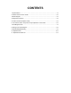
CONTENTS 1. Specifications ··················································································································1-1 2. Names and Functions of Parts ······················································································2-1 3. Block Diagram ···············································································································3-1 4.
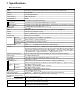
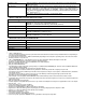
1 Specifications Main Specifications Model No. CF-30CTQAZBM/CF-30CTQEZBM CPU Intel® Core™ Duo Processor L2400 (1.66 GHz, 2 MB*1 L2 cache, 667 MHz FSB) Chipset Intel® 945GM Memory*1*2 512 MB (4096 MB Max.) Video Memory*1*3 Hard Disk Drive UMA (128 MB Max.) *4 80 GB Display Method 13.
Operating System Microsoft® Windows® XP Professional Service Pack 2 with Advanced Security Technologies (NTFS File System) Utility Programs DMI Viewer, Microsoft® Windows® Media Player 10, Adobe Reader, PC Information Viewer, SD Utility, Icon Enlarger, Loupe Utility, Intel® Matrix Storage Manager, Intel® PROSet/Wireless Software*7, Bluetooth™ Stack for Windows® by TOSHIBA*8 , Wireless Switch Utility, Hotkey Settings, Battery Recalibration Utility, Panasonic Hand Writing, InÞneon TPM Professional Package*
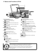
2 Names and Functions of Part F G H I J K K L A EX PC K M N O D E A: Bluetooth Antenna Reference Manual “Bluetooth” B: ExpressCard Slot Reference Manual “PC Card / ExpressCard” C: PC Card Slot Reference Manual “PC Card / ExpressCard” D: Multimedia Pocket Reference Manual “Multimedia Pocket” E: Battery Pack F: Wireless LAN Antenna Reference Manual “Wireless LAN” G: LCD Reference Manual “Touchscreen” H: Fun
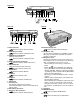
Right side A B C DE F G H I 1394 Rear side Bottom Q J H K L M N O P A: Hard Disk Drive Reference Manual “Hard Disk Drive” B: SD Memory Card Slot Reference Manual “SD Memory Card” C: SD Memory Card Indicator (Blinking: During access) Reference Manual “SD Memory Card” D: IEEE 1394 Interface Connector Reference Manual “IEEE 1394 Devices” E: Smart Card Slot Reference Manual “Smart Card” F: Modem Port Reference Manual “Modem” G: LAN Port Reference Manual “LAN
Touch (PortRep) Serial LPC Bridge USB 2.0 Screen GPS USB1.1 1.5V INTEL Interface Interface IDE DMI Interface HDD PCI AC-link Bridge Serial Buffer Bridge PCI Express Interface INTEL Interface Wireless cinfig CN PATA Finger Print Buffer Internal USB1.1 HUB 1.1/2.0 PATA (1.5Gb/s) SATA 8M SPI BIOS Interface (1.05 ) Interface Graphics DMI DRAM 5.3Gbytes/sec Internal 1.66GHz, FSB 667MHz 2MB L2 Cache Yonah DC Internal USB1.1 Blue-tooth MP 80GB 2.
4 Diagnosis Procedure 4.1.
4.2. Troubleshooting Please take note of the following two points with regard to troubleshooting: 1. Know-how of diagnosis upon occurrence of heavy troubles, e.g. Set cannot be turned ON , Set fails to start , No display on screen , etc. 2. Explanation of each trouble, mainly symptom of trouble in operation. Flow Chart START START Set cannot be supplied with current. Power lamp fails to light up. Pay attention to the following points when in pursuit of the cause of a troubleshooting. 1.
5 Power-On Self Test (Boot Check) Outline of POST The set has a boot check function called POST (Power-On Self Test) in it. The condition of the main body is diagnosed by checking beep sound or error code. Start .............Test begins automatically when power switch is set to ON. Normal finish .....After memory checking, a beep sound is issued once and the set is placed into automatic stop. Note: If no error occurs, nothing is displayed. (No display of OK, etc.
6 List of Error Codes The following is a list of the messages that BIOS can display. Most of them occur during POST. Some of them display information about a hardware device, e.g., the amount of memory installed. Others may indicate a problem with a device, such as the way it has been configured. Following the list are explanations of the messages and remedies for reported problems.
6-2 Troubleshooting 02D0 System cache error - Cache disabled Contact Panasonic Technical Support. 02F0: CPU ID: CPU socket number for Multi-Processor error. 02F4: EISA CMOS not writable ServerBIOS2 test error: Cannot write to EISA CMOS. 02F5: DMA Test Failed ServerBIOS2 test error: Cannot write to extended DMA (Direct Memory Access) registers. 02F6: Software NMI Failed ServerBIOS2 test error: Cannot generate software NMI (Non-Maskable Interrupt).
7 Self Diagnosis Test As for the self-diagnosis test(PC-Diagnostic utility) to use this model, a standard test and the enhancing test by the module of the main body building in are possible. Notes To skip BIOS password Use + key to skip BIOS password or authentication of fingerprint. This key is only for entering DIAG mode. Not available to boot the computer. If customer set "HDD Lock", the DIAG program cannot perform HDD test. *This key is for service purpose only.
2. Operation of PC-Diagnostic Utility -Only the device which can be inspected on the entire screen is displayed. -The item does not appear when the device of wireless LAN etc. is not physically connected. -The movement of the item must use an arrow key or a flat pad. -As for the device under the diagnosis, blue and yellow are alternately displayed at the left of the icon. - The diagnosis result of the device greens at the left of the icon when it is normal, and becomes red when abnormal.
2-1. Selection of tested device -To test only a specific device, "Test" and "Do not test" of each device can be selected. -The device which can select the enhancing test changes in order of "The standard is tested" and "Do not test" whenever the device icon is clicked. Do not test Start the standard test Please begin testing clicking if the selection of the tested device ends. 2-2.
7.1. Test Item and Division of trouble Test item Stanard Enhancing Content of standard test Content of enhancing test Place with possibility of breakdown CPU / SYSTEM CPU is shifted to protected mode, and "Violation of the paging", "Operation of the violation of a privileged instruction", and DMA, INT, TIMER, and the RTC operation are confirmed. CPU / Main board RAM All memory space is tested in a special memory access pattern based on "R.S.T . technology".
Test Item Standard Enhanced Content of Standard Test It is confirmed not to find abnormality in the USB connection of Touch Screen. This test cannot find abnormality of Touch Screen. It is confirmed not to find abnormality in the connection of Main board and Bluetooth module. It is confirmed not to find abnormality in the connection of Main board and Wireless WAN module. It is confirmed not to find abnormality in the legacy FD drive. This test cannot find abnormality of mechanical breakdown. (e.g..
8 Wiring Connection Diagram USB USB PORT PORT CN100 CN102 EXTERNAL DISPLAY PORT EXPANSION BUS CN705 CN101 CN701 SERIAL PORT CN703 CN700 CN702 JK701 I/O PCB USB PCB USB PORT HEAD MICRO PHONE PHONE JK700 BACK LIGHT CN103 TOUCH SCREEN INVERTER PCB ANTENNA PCB LCD CN201 CN1 TS PCB CN2 CN1 CN200 EXT ANT.
9 Disassembly/Reassembly Note: Power off the computer. Do not shut down to the Suspend or hibernation mode. Do not add peripherals while the computer is in the Suspend or hibernation mode; abnormal operation may result. 9.1. 9.1.1. 9.1.2. Disassembly Instructions Preparation Removing the Battery Pack and HDD Pack Before disassembling, be sure to make the following preparations. • Shut down Windows and turn off the power. • Disconnect the AC adaptor.
9.1.3. 9.1.4. Removing the HDD HDD U Case Ass’y HDD FPC Removing the KB Cover, Hinge Cover L, Hinge Cover R and Keyboard HDD Bluetooth PCB Heater Sheet Sheet HDD Damper Ass’y Sheet Hinge Cover L KB Cover Tab Heater HDD L Case Ass’y Hinge Cover R Tab 1. Remove the Screw. 2. Remove the 4 Screws. 3. Release the 2 Tabs, and remove the HDD U Case Ass'y and the HDD L Case Ass'y. 4.
9.1.5. 9.1.6. Removing the KB Cable Cover and LCD Cable Cover Removing the GPS PCB and Bluetooth PCB GPS BT Angle KB Cable Cover GPS PCB LCD Cable Cover to Connector to Connector (CN13) (CN14) Bluetooth PCB Connector(CN25) to Connector (CN25) Keyboard LCD Cable Plate 1. 2. 3. 4. Connector (CN14) Connector (CN13) Disconnect the Cable from the Connector. (CN25) Remove the 4 Screws.
9.1.7. 9.1.8. Removing the DIMM Cover and Bottom Cover Removing the USB PCB and Antenna PCB Tape Connector (CN100) DIMM Cover USB PCB Antenna PCB Antenna Cable (White) DIMM Stopper Base Connector Cover DIMM Heat Plate Antenna Cable (White) DIMM Memory Card Bottom Cover 1. 2. 3. 4. 5. 6. 7. Remove the Screw.
9.1.9. 9.1.10. Removing the PAD PCB Removing the FPC HDD BAT to Connector (CN8) to Connector (CN7) TP PCB Screw Sheet FPC HDD BAT to Connector (CN9) Tape to Connector (CN800) Antenna Cable Sheet Connector (CN801) HDD Cable Cover Tape Pad Protect Sheet to Connector (CN26) Connector(CN10) Pad PCB Connector(CN26) Connector (CN802) Connector (CN8) Tape Connector (CN7) Connector(CN9) 1. Remove the Tape and disconnect the Cable from the Connector.
11. 12. 13. 14. 15. 16. 17. 18. 19. to Connector(CN700) to Connector(CN701) Connector(CN700) Main Chasis Connector (CN31) (CN400,CN401) Remove the 2 Screws. Remove the 2 Screws. Remove the MP Guide. Remove the MP PCB. Remove the Coin Battery Cushion. Disconnect the Cable from the Connector. (CN19) Remove the Coin Battery. Remove the Tape. Disconnect the 2 Cables from the 2 Connectors.
9.1.12. Removing the SD PCB, Express Card and PCMCIA Card 9.1.13. Removing the I/O PCB Connector (CN701) Connector (CN700) Connector Cover Express Card I/O PCB Lib Cover PCMCIA Card 1. 2. 3. 4. 5. 6. SD PCB 1. 2. 3. 4. Remove the 2 Screws. Remove the SD PCB. Remove the 4 Screws. Remove the Express Card. Remove the 4 Screws. Remove the PCMCIA Card. Open the Connector Cover and Lid Cover.
9.1.14. Removing the Palm Top Cover Sheet, Palm Top Cover, Touch Pad Adhesion Seat, Touch Pad, Touch Pad SW Knob, LED PCB and SW LED PCB 9.1.15. Removing the Handle and Power SW Handle Base L Handle Base R Palm Top Cover Sheet Handle Palm Top Cover WM SW Touch Pad Adhesion Seat PW LED Sheet Touch Pad PW LED PCB LED PCB Touch Pad SW Knob Power SW 1. Remove the 2 Screws , and remove the Handle Base L and R. 2. Remove the Handle. 3.
9.1.16. Removing the Display Unit 9.1.17. Removing the LCD Rear Cabinet, Hinge L and R Display Unit left LCD Cover Side Cover LCD Rear Cabinet Wireless Antenna Corner Cover LCD Latch Hinge L right LCD Cover Side Cover Wireless Antenna Corner Cover Hinge R 1. Remove the 2 Screws and the 4 Screws . 2. Remove the Display Unit. LCD Front Cabinet 1. 2. 3. 4. 5.
9.1.18. Removing the Inverter PCB, TS PCB and LCD Unit 9.1.19. Removing the Antenna PCB L and R LCD Rear Cabinet Ass’y W-LAN ANT Cover L Antenna PCB L C LCD Drop Holder Connector (CN201) TS PCB Connector (CN200) A B LCD Drop Holder Inverter PCB LCD Unit 1. 2. 3. 4. A Remove the 4 Screws . Remove the W-LAN ANT Cover L and R. Remove the 2 Screws. Remove the Antenna PCB L and R.
9.2. 9.2.1. Reassembly Instructions Attention when CF-30 series is repaired • Please execute writing BIOS ID when you exchange the Main Board. • Parts (Sheet and rubber) etc. related various the Conductive Cloth and Heat Spreader cannot be recycled. Use new parts. 9.2.2. Setting the Antenna PCB L and R 1. Set the Antenna PCB L and R using the 2 Screws. 2. Fix the W-LAN ANT Cover L and R using the 4 Screws.
9.2.3. 1. 2. 3. 4. 5. Setting the Inverter PCB, TS PCB and LCD Unit Set the LCD Unit to the LCD Front Cabinet in order. Attach the 2 drop holders. Connect the Cable to the Connector. (CN200,CN201) Connect the 3 Cables to the 3 Connectors. Fix the Inverter PCB using the 2 Screws.
Q Assembly of LCD Unit * Notes: 1. Apply the load when attaching the parts. 20N to 30N (2 to 3Kgf)/cm2 Confirm that the LCD Cushion is not wrapped. LCD Drop Holder Insertion Attach the Inverter MIL Shierd LCD Front Ass’y Match to the LCD edge and attach it. Clearance : 2 mm or less LCD Drop Holder Insertion 0 0.5mm Attach the TS Controller Flex Stiffening Plate Edge Release Paper B TS Flex Insertion Release Paper A Attach the Tape * Notes: 1. Apply the load when attaching the parts.
9.2.5. Setting the Display Unit 1. Fix the Display Unit using the 4 Screws. No1 to No4 2. Fix the Display Unit using the 2 Screws. No1, No2 Display Unit Note: Tighten the Screws in the numbered order (No1 to No2). Tighten the Screws in the numbered order (No1 to No4). No.1 No.4 Screws : DRYN4+J10FKL Screws : DXSB4+15FNLB No.3 No.2 No.1 No.2 9.2.6. 1. 2. 3. 4. Setting the Handle and Power SW Set the WM SW using the 2 Screws.
9.2.7. Setting the Palm Top Cover Sheet, Palm Top Cover, Touch Pad Adhesion Seat, Touch Pad SW Knob, LED PCB And SW LED PCB 1. Set the SW LED PCB. 2. Attach the Power LED Packing Sheet to the LED Spacer Sheet. 3. Attach the LEDX6 Spacer Sheet on the SW LED PCB. 4. Fix the SW LED PCB using the Screw. 5. Attach the PW LED Sheet. 6. Pass the Cable of LED PCB through the hole 1 on the Top Cabinet, then set the LED PCB. 7. Attach the LES Spacer Sheet on the LED PCB. 8.
Q Assembly of Power SW Top Attach the Battery Cushion Connection Direction Bottom Battery Pack Insertion Slot Cable Power Connection * Notes: 1. Apply the load when attaching the parts. 20N to 30N (2 to 3Kgf)/cm2 12 CAB Wall 2 Connection Direction 3 25 5 2 Tighten of Screw Attach the Battery Slide Sheet (on Battery Cushion) FPC Power SW is set Power SW LED Panel is set Avoid air leaking into it. Avoid coming off 4 corners. Safety Working Fit to the line.
9.2.8. 9.2.9. Setting the I/O PCB 1. Open the Connector Cover and Lid Cover. 2. Fix the I/O PCB using the 4 Screws. No1 to No4 3. Fix the I/O PCB using the 4 Screws. No1 to No4 Connector (CN701) Connector (CN700) Connector Cover Setting the SD PCB, Express Card and PCMCIA Card 1. Fix the PCMCIA Card using the 4 Screws. 2. Fix the Express Card using the 4 Screws. 3. Fix the SD PCB using the 2 Screws. I/O PCB No.2 No.2 No.2 No.1 No.3 No.4 No.
9.2.10. Setting the Main PCB 17. Attach the Tape. 1. Fix the Main PCB using the 7 Screws and Screw. No1 to No8. 2. Set the Modem Cable. 3. Connect the Cable to the Connector (J2) and fix the MDC. 4. Attach the Tape. 5. Attach the 1394 Sheet. 6. Fix the MDC using the 2 Screws. 7. Fix the Modem LAN Case using the 2 Screws. 8. Attach the 2 Modem Cable Sheets. 9. Fix the ICH Plate using the 3 Screws and Screw .
24. Fix the Screw. 25. Attach the TOP Screws. TOP Screw Sheet Connector (CN17) Connector (CN27) Note: Tighten the Screws in the numbered order (No1 to No8). Tighten the Screws in the numbered order (No1 to No6).
Q Assembly of LAN, Modem and MDC * Notes: 1. Apply the load when attaching the parts. 20N to 30N (2 to 3Kgf)/cm2 Order of fixing Tighten of Screw Tighten of Screw Screw Screw Modem LAN Case is installed. 5 Pass the Cable to the back from the hole of the A side. 1 15 1 LAN Cable is installed. Attach space Separate from the coil. Modem Cable is installed.
9.2.11. 1. 2. 3. 4. Setting the PAD PCB Fix the PAD PCB using the 2 Screws. Attach the TP PCB Screw Sheet. Connect the Cable to the Connector. (CN802) Connect the Cable to the Connector (CN801) and attach the Tape. TP PCB Screw Sheet Tape Screws : DRQT26+D3FKL Connector (CN801) Pad PCB Connector (CN802) Q Assembly of PAD PCB * Notes: 1. Apply the load when attaching the parts.
9.2.12. Setting the FPC HDD BAT 1. 2. 3. 4. 5. 6. 7. 8. 9. 10. Fix the FPC HDD BAT using the Screw. Connect the 2 Cables to the 2 Connectors. (CN7,CN8) Connect the Cable to the Connector. (CN800) Attach the PAD Protect Sheet. Connect the Cable to the Connector. (CN9) Attach the Tape. Connect the 2 Cables to the 2 Connectors. (CN10,CN26) Attach the Tape. Attach the Antenna Cable Sheet on the Main PCB. Fix the HDD FPC BAT using the 5 Screws.
1. Set HDD Guide and fix with Screw. 2. Fix with Screw. 3. Apply tetra coating to each connector pin. Tighten of Screw Direction A View FPC HDD Battery is set A Do not Fold. (R1 4) Direction B View B C Battery HDD Connector Angle is set HDD Guide is set This Connector does not need tetra coating.
Insert the Plug into the Socket A The terminal of the antenna Relay Circuit Board Ass’y cable must not come in contact with this terminal. Cable (Put it on the metal fittings side. ) Insert FPC into Relay Circuit Board Ass’ys socket Figure seen from direction of arrow of A Mountain Fold (Straight Line) Lock after FPC insertion Valley Fold (Dotted Line) FPC FIG FPC OK The attention of folding : Breakage countermeasure. 1,The bending inside is R0.5 1 2,Don’t mistake a bending direction.
Q Assembly of USB PCB and Antenna PCB * Notes: 1. Apply the load when attaching the parts. 20N to 30N (2 to 3Kgf)/cm2 Safety Working Safety Working Attach the Tape Attach the Antenna Cable Sheet Fit to the groove. Difference : 1 or less Set on the top. Order of fixing Screw Screw Process the cable from LCD. Tighten of Screw Antenna Cable Plate is set W-LAN Cable Connection EXT Antenna PCB is set Connect the coaxial cable from LCD.
9.2.14. Setting the DIMM Cover and Bottom Cover 1. Set the Bottom Cover. 2. Fix the Bottom Cover using the 6 Screws. No1 to No6 3. Fix the Bottom Cover using the 13 Screws. No1 to No13 4. Set the DIMM memory card. 5. Attach the DIMM Heat Plate. 6. Fix the DIMM Stopper Base using the 2 Screws. 7. Fix the DIMM Cover using the 5 Screws. Screws : DRHM0002ZA Screws : DRQT26+D4FKL Screws : DRQT26+E4FKL Screws : DRSB3+8FKL No.5 No.2 No.4 No.3 DIMM Cover No.
Q Preparation of DIMM Cover * Notes: 1. Apply the load when attaching the parts. 20N to 30N (2 to 3Kgf)/cm2 DIMM Cover is set 0 0.5mm Attach the DIMM Cover Cushion 0 0.5mm Attach the DIMM Cover Spacer 0 0.5mm 0 0.5mm Safety Working * Notes: Keyboard Cable Cover is installed 1. Apply the load when attaching the attaching parts. 20N to 30N (2 to 3Kgf)/cm2 4 6mm 2.5mm Attach the CD Edge Sheet Attach the LCD Cable Cover Cushion 1mm Attach the CD Edge Sheet 4 LCD Cable Cover is set 1.
9.2.15. Setting the GPS PCB and Bluetooth PCB 1. Fix the GPS BT Angle and GPS PCB using the 2 Screws. 2. Connect the Cable to the Connector on GPS PCB. 3. Fix the GPS Ass’y using the 4 Screws. 4. Connect the Cable to the Connector. (CN25) GPS BT Angle GPS PCB Screws : DFHE5025XA Screws : DXQT2+F3FNL Bluetooth PCB Connector(CN25) to Connector (CN25) Q Cautions for Setting GPS ASSY and BT PCB ASSY * Notes: 1.
9.2.16. Setting the KB Cable Cover, Keyboard and LCD Cable Cover 1. Set the Keyboard onto the Computer. 2. Connect the 2 Cables to the 2 Cables. (CN13,CN14) 3. Fix the KB Cable Cover using the 7 Screws. No1 to No7 4. Set the LCD Cable Plate. 5. Fix the LCD Cable Cover using the 3 Screws. No1 to No3 Note: Tighten the Screws in the numbered order (No1 to No7). Tighten the Screws in the numbered order (No1 to No3). No.3 No.5 No.7 No.1 No.4 to Connector No.
7.2.17. Setting the KB Cover, Hinge Cover L, Hinge Cover R and Keyboard 1. Insert the front hooks of the Keyboard to the Top Cabinet in order, and set the Keyboard. 2. Fix the Hinge Cover L and R using the 4 Screws No1 to No3 3. Fix the Hinge Cover L and R using the 2 Screws. No1, No2 4. Fix the Bluetooth PCB using the Screw. 5. Fix the KB Cover using the 4 Screws. No1 to No4 No.3 No.1 Bluetooth PCB No.2 No.
Q Preparation oh HDD ASSY * Notes: 1. Apply the load when attaching the parts. 20N to 30N (2 to 3Kgf)/cm2 20 10 1 1 7 1 Fit to the corner. 0 1 Attach the HDD Tape L HDD is set 0 1 Attach the HDD Tape S Turn it to the board side (back side). 1. Do not gouge when inserting and removing the socket. 2. Do not drop HDD or add any impacts on it. 3. Insert CN into the end firmly. 4. Apply the load when attaching the parts.
* Notes: 1. Apply the load when attaching the parts. 20N to 30N (2 to 3Kgf)/cm2 HDD Damper Ass’y Push and bend Make sure the product with black sheet on the yellow sponge. Fold the FPC from the board edge. HDD Ass’y HDD Set Insert after removing the Release Paper of the two-sided tape. Remove the Release Paper on the back, close and attach it. Attach it to HDD closely not to loosen. * Notes: 1. Apply the load when attaching the parts.
When attaching HDD Cushion Plate and HDD Cushion (Black), set the bending part of the metal plate up. * Notes: 1. Apply the load when attaching the parts. 20N to 30N (2 to 3Kgf)/cm2 1 HDD Thermal Plate 1 2 0 1 2 1 2 1 0 1 2 Do not bend it at a sharp angle to put natural R. HDD Cushion (Black) Metal Plate To the level of attaching closely in this range Fold back matching 4 corners.
* Notes: 1. Apply the load when attaching the parts. 20N to 30N (2 to 3Kgf)/cm2 (4) (4) 11 1 Right and left position: Match to the center Top and bottom position: Match the edge of the base material transparent sheet to the bottom side A (20) HDD Side Damper is installed A (0) HDD Side Damper (2) B B 0 0.
Set the CN side first, and then set the TAB side pushing to the A direction. SATA Guide Set HDD Ass’y insertion SATA Guard is installed A Insert to make the Cushion on the HDD inside of the Cushion on the lower case. Avoid getting HDD under the side damper when inserting HDD NG * Notes: Order of fixing Screw Screw 1. Apply the load when attaching the parts.
9.2.19. Setting the Battery Pack and HDD Pack 1. Set the HDD Pack. 2. Set the Battery Pack.
10 E xploded V iew K77 K82 B N5 K78 K76 B N2 B K32 N5 E1001 B N5 B N5 A A N4 A N4 K35 K33 K73 N4 B K70 K95 K93 K115 B K29 K75 N5 B K74 K73 K116 B N4 N4 N4 K73 E24 B N2 K16 K87 E4 K84 K90 K71 K162 E23 E21 E13 K92 K24 B K109 B K19 N7 N4 G B B N4 B N4 N4 B K30 N4 N10 B N4 K23 K35 V B N4 V G K17 N10 K1 K1-1 Screw tightening torque B F G I L 0.19 + _ 0.02 N.m + 0.2 kgf.cm) (2.0 _ 0.45 + _ 0.05 N.m (4.5 + _ 0.5 kgf.cm) 0.49 + _ 0.05 N.m (5.
R R K2-16 K2-16 K2-3 K2-6 K2-5 K2-5-3 K2-10 K2-6-2 R K2-6-5 K2-6-1 K2-5-1 K2-3-4 B K2-3-1 K2-10-8 K2-5-2 K2-3-3 K2-10-1 K2-6-4 K2-10-3 L K2-3-2 K2-6-1 K2-5-4 L K2-39 B R K2-6-3 K2-6-3 R K2-39 K2-10-8 K2-10-2 K2-10-5 K2-10-1 Q N1 K2-8 B K2-8-10 K2-8-2 K2-8-1 K2-8-5 K2-8-4 B K2-8-10 K2-8-1 K104 K101 K100 K81 R K2-39 K2-8-6 K2-8-3 K2-8-7 K2-8-9 K2-14 K2-36 K2-23 K2-4-3 K2-4-1 K2-17 R K2-16 K2-4-2 K2-8-3 K2-13 K2-4-4 L K2-22 L K2-8-11 T K2-38 K2-14 K2-17 K2-1
F N14 A N15 F N14 A N11 A N15 A N11 A N3 K159 K156 K83 V W K158 K157 K120 E1 K2-11 K2-29 E19 A N5 E8 K117 E38 K97 E22 K97 K2-12 K2-19 K91 K130 K2-28 R K2-40 V B N4 K38 E10 B N4 B N4 N11 A N11 B N11 E20 B N17 N17 K99 A A A C E F G H I L M N P A N22 0.19 + _ 0.02 N.m (2.0 _ + 0.2 kgf.cm) E33 0.216 _ + 0.0196 N.m A N22 (2.2 _ + 0.2 kgf.cm) 0.314 _ + 0.0196 N.m K133 (3.2 + _ 0.2 kgf.cm) K134 0.49 + _ 0.05 N.m (5.0 + _ 0.5 kgf.cm) K146 0.441 _ + 0.049 N.m K138 (4.5 + _ 0.5 kgf.
S N12 S N12 E2 K41 K42 K40 E6 K20 E14 A N11 K2-33 K2-32 R R K2-39 K2-39 K28 K2-34 K8 R K3 K3-8 K3-2 K7 R K3-8 K3-5 K3-3 B N6 X K3-4 K3-6 K3-1 K85 K18 K6 R K3-8 K31 B N1 B N1 P N8 B B N6 B N1 N6 B N6 B N6 B N1 B N1 X P N8 K85 K85 B N6 K4 B N6 B N6 B N6 B P B N6 N6 P N8 N8 K85 P N8 B N6 Screw tightening torque B K5 P R K80 10-4 S 0.45 + _ 0.05 N.m (4.5 _ + 0.5 kgf.cm) 0.8 + _ 0.1N.m (8.0 + _ 1.0 kgf.cm) 0.3 + _ 0.05 N.m (3.0 + _ 0.5 kgf.cm) 0.
K36 K59 K36 K50 K9 K53 K53 K61 K9-2-1 K53 K9-2-1-1 K9-2 K9-2-2 K50 K9-2-3 K66 K60 G N9 K63 K9-1-3 K10 K62 K65 K10-1 K10-2 K9-1-2 G K9-1-4 K12 K11 B N5 K49 E16 K91-3 K91-3 K9-4 K9-3 K9-1-3 K15 G N9 Screw tightening torque A K9-1 K9-1-1 K9-1-3 G K9-1-4 K9-1-3 10-5 + 0.02 N.m 0.19 _ (2.0 + _ 0.2 kgf.cm) + 0.50 N.m B 0.45 _ (4.5 + _ 0.5 kgf.cm) F 0.441 + _ 0.049 N.m (4.5 + _ 0.5 kgf.cm) + 0.20 N.m G 1.47 _ (15 + _ 2.0 kgf.cm) H 1.30 _ + 0.17N.m (13.0 + _ 2.0 kgf.
E35 K54 E35-2 E35-5 E15 E7 A E35-10 K56 E35-1 E35-3 E35-8 E35-4 E35-6 E35-3 E35-7 E35-4 A E35-10 E35-9 Screw tightening torque A B C D E 10-6 0.19 + _ 0.02 N.m + 0.2 kgf.cm) (2.0 _ 0.45 + _ 0.05 N.m (4.5 _ + 0.5 kgf.cm) 0.216 + _ 0.0196 N.m (2.2 + _ 0.2 kgf.cm) 0.314 + _ 0.0196 N.m (3.2 + _ 0.2 kgf.cm) 0.49 + _ 0.05 N.m (5.0 + _ 0.5 kgf.
B B N7 N2 B K44 B N2 N7 K57 B K55 B N2 N2 B K58 N7 K55 B N2 B E36 B B N2 N7 N7 E37 K79 B N7 G K55 B N7 N13 K13-2 K13 B N7 K45 K46 K55 K52 B N7 K55 B N7 K47 K55 K13-1 G N13 K55 B N7 B N7 Screw tightening torque A B C D G O 10-7 0.19 + _ 0.02 N.m (2.0 + _ 0.2 kgf.cm) 0.45 + _ 0.05 N.m (4.5 + _ 0.5 kgf.cm) 0.216 + _ 0.0196 N.m (2.2 + _ 0.2 kgf.cm) 0.314 + _ 0.0196 N.m (3.2 + _ 0.2 kgf.cm) 1.47 + _ 0.20 N.m (15 + _ 2.0 kgf.cm) 0.49 + _ 0.05 N.m (5.0 + _ 0.5 kgf.
Replacement Parts List Comparison Table Note : Important Safety Notice ! mark have special characteristics important for safety. Components identified by When replacing any of these components, use only manufacturer's specified parts. CF-30CTQAZBM (2006/12/14) PART NO. REF.