Order No. CPD0611208C1 Notebook Computer CF-Y5 This is the Service Manual for the following areas. M …for U.S.A. and Canada Model No. CF-Y5LWVYZ 1 2 1: Operation System B: Microsoft® Windows® XP Professional 2: Area M: Refer to above area table © 2006 Matsushita Electric Industrial Co., Ltd. All rights reserved. Unauthorized copying and distribution is a violation of law.
WARNING For U.K. This apparatus must be earthed for your safety. To ensure safe operation the three-pin plug must be inserted only into a standard three-pin power point which is effectively earthed through the normal household wiring. Extension cords used with the equipment must be three-core and be correctly wired to provide connection to earth. Wrongly wired extension cords are a major cause of fatalities.
LASER SAFETY INFORMATION For U.S.A. Class 1 LASER-Product This product is certified to comply with DHHS Rules 21 CFR Subchapter J. This product complies with European Standard EN60825 (or IEC Publication 825) For all areas This equipment is classified as a class 1 level LASER product and there is no hazardous LASER radiation. Caution: (1) Use of controls or adjustments or performance of procedures other than those specified herein may result in hazardous radiation exposure.
CONTENTS 1. Specifications 7 2. Names and Functions of Parts 10 3. Block Diagram 12 4. Diagnosis Procedure 13 5. Power-On Self Test (Boot Check) 15 6. List of Error Codes 16 7. Self Diagnosis Test 18 8. Wiring Connection Diagram 23 9. Disassembly/Reassembly 24 10. Exploded View 80 11.
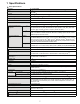
1 Specifications Useful Information Getting Started Main Specifications Model No. CPU/ Secondary cache memory CF-Y5LWVYZBM Chip Set Mobile Intel® 945 GMS Express chip set Main Memory 512 MB*1, DDR2 SDRAM (1536 MB*1 Max.) Video Memory UMA (128 MB*1 Max.)*2 Hard Disk Drive 60 GB*3 CD/DVD Drive USB 2.
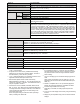
CF-Y5LWVYZBM *23 Power Consumption Approx. 35 W*24 / Approx. 60 W (maximum when recharging in the ON state) Physical Dimensions (W × H × D) 309.6 mm × 28 mm (at the front)/44.5 mm (at the rear) × 245.5 mm (excluding protrusion) {12.2 " × 1.1 " / 1.8 " × 10.0 "} Weight*25 Approx. 1530 g {3.4 lb.
*12 *13 *14 Getting Started *15 *16 *17 20-M-2-1 Appendix Troubleshooting Useful Information *18 When using an external display with a resolution of 2048 x 1536 dots, use a display that supports a 60Hz refresh rate. If an external display that does not support a 60Hz refresh rate is used, images may not be displayed properly. Some devices cannot be used depending on the port type. For information on TPM, click [start] - [Run] and input “c:\util\drivers\tpm\README.
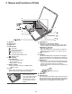
2 Names and Functions of Parts A B C D E F J G K H L M N I A :Speakers B :Function Key C :Keyboard D :LED Indicator : Caps lock : Numeric key (NumLk) : Scroll lock (ScrLk) : Hard disk drive status ECO : Economy Mode (ECO) status : Battery status E : Power Switch Power Indicator • Off: Power off/Hibernation • Green: Power on • Blinking green: Standby F : Wireless Switch “Wireless LAN” G :Latch When closing the display, press down firmly from above until the
H I A B M C J EXT. D K E F G N A :DC-IN Jack B :Ventilation Hole C :External Display Port If the Mini Port Replicator is connected to the computer, connect the external display to the external display port on the Mini Port Replicator. You cannot use the external display port on the computer. D :Mini Port Replicator Connector Connect the Mini Port Replicator (optional). E : Microphone Jack A condenser microphone can be used.
3 Block Diagram Internal Core Frequency HFM=1.6 GHz Hz/LFM= /LFM=1.0 HFM=1.66 1.66 G Hz /LFM=1.0 GHz GHz (High Model) HFM=1.2 1.2 GHz/LFM= GHz/LFM=800 HFM= 800 MHz (Low Model) VCC Core Yonah LV Dual Core Yonah ULV Single Core HFM=1.0V .2125V/ 1.0V V HFM=1.0V1.0V-1.2125 V/ LFM=0.7625V LFM=0.7625V0.7625V-1.0 Included L2-Cache 2M (479pin FCBGA) Deeper Sleep=0.55V 0.85V V (H (High Model)) Sleep=0.55V0.55V-0.85 igh Model HFM=0.85V 0.85V--1.1 1.1V/ 0.8--1. 1.0 HFM= 0.85V V/ LFM=0.8 LFM=0.
4 Diagnosis Procedure 4.1.
4.2. Troubleshooting Please take note of the following two points with regard to troubleshooting: 1. Know-how of diagnosis upon occurrence of heavy troubles, e.g. Set cannot be turned ON , Set fails to start , No display on screen , etc. 2. Explanation of each trouble, mainly symptom of trouble in operation. Flow Chart START START Set cannot be supplied with current. Power lamp fails to light up. Pay attention to the following points when in pursuit of the cause of a troubleshooting. 1.
5 Power-On Self Test (Boot Check) Outline of POST The set has a boot check function called POST (Power-On Self Test) in it. The condition of the main body is diagnosed by checking beep sound or error code. Start .............Test begins automatically when power switch is set to ON. Normal finish .....After memory checking, a beep sound is issued once and the set is placed into automatic stop. Note: If no error occurs, nothing is displayed. (No display of OK, etc.
6 List of Error Codes The following is a list of the messages that BIOS can display. Most of them occur during POST. Some of them display information about a hardware device, e.g., the amount of memory installed. Others may indicate a problem with a device, such as the way it has been configured. Following the list are explanations of the messages and remedies for reported problems.
Troubleshooting 02D0 System cache error - Cache disabled Contact Panasonic Technical Support. 02F0: CPU ID: CPU socket number for Multi-Processor error. 02F4: EISA CMOS not writable ServerBIOS2 test error: Cannot write to EISA CMOS. 02F5: DMA Test Failed ServerBIOS2 test error: Cannot write to extended DMA (Direct Memory Access) registers. 02F6: Software NMI Failed ServerBIOS2 test error: Cannot generate software NMI (Non-Maskable Interrupt).
7 Self Diagnosis Test As for the self-diagnosis test(PC-Diagnostic utility) to use this model, a standard test and the enhancing test by the module of the main body building in are possible. Notes To skip BIOS password Use + key to skip BIOS password or authentication of fingerprint. This key is only for entering DIAG mode. Not available to boot the computer. If customer set "HDD Lock", the DIAG program cannot perform HDD test. *This key is for service purpose only.
2. Operation of PC-Diagnostic Utility -Only the device which can be inspected on the entire screen is displayed. -The item does not appear when the device of wireless LAN etc. is not physically connected. -The movement of the item must use an arrow key or a flat pad. -As for the device under the diagnosis, blue and yellow are alternately displayed at the left of the icon. - The diagnosis result of the device greens at the left of the icon when it is normal, and becomes red when abnormal.
2-1. Selection of tested device -To test only a specific device, "Test" and "Do not test" of each device can be selected. -The device which can select the enhancing test changes in order of "The standard is tested" and "Do not test" whenever the device icon is clicked. Do not test Start the standard test Please begin testing clicking if the selection of the tested device ends. 2-2.
7.1. Test Item and Division of trouble Test item Stanard Enhancing Content of standard test Content of enhancing test Place with possibility of breakdown CPU / SYSTEM CPU is shifted to protected mode, and "Violation of the paging", "Operation of the violation of a privileged instruction", and DMA, INT, TIMER, and the RTC operation are confirmed. CPU / Main board RAM All memory space is tested in a special memory access pattern based on "R.S.T . technology".
Test Item Standard Enhanced Content of Standard Test It is confirmed not to find abnormality in the USB connection of Touch Screen. This test cannot find abnormality of Touch Screen. It is confirmed not to find abnormality in the connection of Main board and Bluetooth module. It is confirmed not to find abnormality in the legacy FD drive. This test cannot find abnormality of mechanical breakdown. (e.g.. Head, Motor) It is confirmed not to find abnormality in access to VRAM with VESA.
8 Wiring Connection Diagram Connection Cable عConnection Cable PAD FFC SW FFC DRIVE MAIN FPC LCD Cable DC IN Cable Speaker Cable L㧒R MODEM Cable LAN Cable Antenna PCB Unit R Antenna PCB Unit L USB FPC HDD FPC Unit Bluetooth Antenna PCB Unit Parts on Bottom Side ̪4 LCD DFJK12U112BB DFJK20T108BB DFJK9022ZA DFJS1021ZB DFJS1022YA DFJS1023ZA DFJS1024ZA DFJS1025ZA DL3UP1537AAA DL3UP1538AAA DFUP1522YA DL3UP1521AAA DL3UP1585BBA ̪1 ̪2 ̪3 ̪4 ̪5 ̪6 ̪7 ̪8 ̪9 ̪10 ̪11 ̪12 ̪13 Direct connection Connectors Spe
9 Disassembly instructions 9.1. Disassembly Flow Chart Main Unit 9.2.1. Preparation 1. End the Windows. 2. Turn off the Power, and then remove the AC Adaptor or Battery Pack. 3. Remove any optional DIMM Memory Cards or PCMCIA Cards. 4. Remove any other peripherals or Connected Devices. 9.2.2. 9.2.3. HDD Keyboard 9.2.4. Top Case 9.2.5. 9.2.7. SUB DVD 9.2.9. FAN Solenoid 9.2.6. 9.2.8. Touch Pad / LCD Knob 9.2.10. Speaker 9.2.12. 9.2.11. Drive Unit Main Board 9.2.14. Antenna Board (L), (R) 9.
9.2. Disassembly lnstructions 9.2.3. Removing the Keyboard 9.2.1. Preparation Preparation : perform the section 9.2.1. first. Attention: Before disassembly, be sure to perform the following steps. 1. End the Windows. 2. Turn off the power and then remove the AC adaptor. 3. Slide the hooks (A) and then remove the battery Pack. 4. Remove the screw (A) and then remove the DIMM cover. (Remove if the DIMM memory is equipped with) Screw (A) : XSB2+4FNL (N14) Lithium Ion Battery Pack 1.
5. KB side cover (L) is adjusted to the upper part as well as KB side cover (R), the minus clock driver removes hook (C-1) in the hook position from the space with the bottom case, rotates to the keyboard side, and detaches. Hook (C-1) Hook (C-1) KB Side Cover (L) Hook (C-2) LCD Unit Hook (C-2) 9.2.4. Removing the Top Case Preparation : perform the section 9.2.1., 9.2.3. first. 1. Remove the 2 screws (E) and 2 foot rubber backs. Screw (E) : XTB26+10GFN (N12) 2. Remove the 5 screws (F).
8. The disk cover shaft is removed and pulling out disk cover is removed from the disk cover. Disk Cover 10. CN26 (FAN) and CN15 (SP) are removed. A top case is lifted and FFC (PAD), FFC (DRIVE) and CN27 (solenoid) are removed and then the top case is removed. Disk Cover Shaft CN15 CN26 Top Case Solenoid Cable 9. Remove the 8 screws (J), 3 screws (K), 3 screws (L), 4 screws (M) and 1 screw (N).
9.2.6. Removing the Touch Pad / LCD Knob 9.2.7. Removing the Solenoid / Disc Cover Lock Preparation : perform the section 9.2.1., 9.2.3. and 9.2.4. first. 1. The pad top ring fixed to the pad cover by the both sides tape is removed, and remove the screw (P). Screw (P) : DXHM0057ZA (N5) Preparation : perform the section 9.2.1., 9.2.3. and 9.2.4. first. 1. Remove the solenoid line hold sheet and cable fixed sheet. Solenoid line hold sheet : DFHR3D20ZA (K122) 2.
9.2.8. Removing the Speaker (L), (R) 9.2.9. Removing the FAN Preparation : perform the section 9.2.1., 9.2.3. and 9.2.4. first. 1. Peel off the 5 line hold sheet 1, the 4 brims of the Preparation : perform the section 9.2.1., 9.2.3. DVD PWB sheet, and remove the speaker (L). Line hold sheet 1 : DFHR3D21YA (K123) DVD PWB sheet : DFMX1229ZA (K161) and 9.2.4. first. 1. Remove the KB heat spreader and the heat spreader. 2.
9.2.10. Removing the Drive Unit Preparation : perform the section 9.2.1., 9.2.3. and 9.2.4. first. 1. Peel off the tape from the connector. 3. Disconnect the LCD connector (CN9) (CN10), DC-IN connector (CN601) and FFC (CN4) (CN6) (CN18) (CN8). 2. DVD FFC is removed from connector (CN501), and the drive unit is lifted from the bottom case, and the gasket is peeled off and then remove the drive unit.
9.2.12. Removing the Bluetooth-USB PCB Unit (with BT) / Bluetooth Antenna PCB Unit Preparation : perform the section 9.2.1., 9.2.3. and 9.2.4. first. 1. Remove the screw (V). Screw (V) : DXQT2+D25FNL (N6) 2. Remove the USB FPC from the tape and CN910, and then remove the bluetooth-USB PCB unit. 9.2.14. Removing the Antenna Board Unit (L), (R) Preparation : perform the section 9.2.1., 9.2.3., 9.2.4., 9.2.10. and 9.2.11. first. 1.
9.2.15. Removing the Wireless LAN Module 9.2.17. Removing the Card Bus Ejector Preparation : perform the section 9.2.1., 9.2.3., 9.2.4. and 9.2.11. first. 1. Remove the 2 screws (X). Preparation : perform the section 9.2.1., 9.2.3., 9.2.4. and 9.2.11. first. 1. Remove the 1 screw (Z) from connection side of Screw (X) : DXQT2+D25FNL (N6) 2. Wireless LAN module is floated in the connector fulcrum and removed. wireless LAN.
9.2.18. Removing the LCD Unit 9.2.19. Removing the Hinge Cover (L), (R) Preparation : perform the section 9.2.1., 9.2.3. and 9.2.4. first. 1. Remove the 1 screw (a). Preparation : perform the section 9.2.1., 9.2.3., 9.2.4. and 9.2.18. first. 1. Remove the 2 screws (c) and then remove the hinge Screw (a) : DXQT2+E6FNL (N10) 2. Remove the DC-IN jack plate, DC MDM cover and FAN sheet. FAN sheet : DFMY0428ZA (K65) 3. Peel off the main PWB sheet and remove the connector (CN9), (CN10) of the main board.
9.2.21. Removing the LCD Cable / Inverter Board 2. The intuition combination part of LCD rear case (21 places) is separated with LCD front case. Hook position LCD Rear Preparation : perform the section 9.2.1., 9.2.3., 9.2.4., 9.2.18. and 9.2.20. first. 1. Peel of the damper, conductive cloth, inverter tape and the tape. Inverter tape : DFHR3E07ZA (K18) 2. Remove the hinge (L), (R). 3. LCD Ccable is removed from LCD unit board (CN101), and connector (CN1) is removed from inverter board.
9.3. Reassenbly instructions 9.3.1. Attention when CF-Y5L series is repaired - Please execute writing BIOS ID when you exchange the main board. - Parts (sheet and rubber) etc.related various the conductive cloth and heat spreader cannot be recycled.Use new parts. 9.3.2. Assembly knowhow of the LCD 9.3.2.1.
9.3.2.3. Putting LCD Side Rubber / LCD Side Damper (LCD handling attention) -Do not take out the vicinity of the center of the lamp side having when you take out LCD of the packing box. (Because there is a possibility that the transformation of the lamp reflector etc. occur) -Take out right and left both ends of the lamp side having when you take out LCD. Affixes it between the length walls.
9.3.2.4. Putting LCD Magnet (Attention) -The LCD Front is installed in the receiving stand, and works. Refer to A chart. When inserting in the Front Case, it is noted not to roll the cushion The both sides tape flaking off paper is peeled off, and affixes to Front Case The LCD Magnet is affixed to the dotted line part.(Affix on the plate side) When inserting in the Front Case, it is noted not to roll the cushion LCD Magnet LCD Safety Work Fit to inside surface.
Inverter Case Inverter Board is affixed in a 0 1mm both sides tape externals match Affixes fit to rib Inverter tape affixation without transforming.(Room is given) The tape is pulled too much and LCD Front Case is transformed. Inverter Tape Rib Matches and externals are affixed So as not to transform LCD Front Case, affixes.(Refer to a left chart) Connection The both sides tape flaking off paper is affixed to the peel connector.
9.3.2.7. Assembly of the Hinge (L), (R) 9.3.2.8.
9.3.2.9. Assembly of the LCD Rear / LCD Front 9.3.2.10.
9.3.3. Assembly knowhow of the Main Board 9.3.3.1.
9.3.3.2. Putting MCH Sheet / Heat Spreader Bottom Running aground do not be on DAI The flaking off paper in which "5011" is displayed is peeled off and then affixes to MCH. MCH externals standard 0 1mm Safety work Processes along the DIMM connector Coil externals standard. Thing in which affixation does not exist in coil. MCH externals standard 0 1mm Coil externals standard Line Hold Sheet Safety work Line Hold Sheet 1 Affixes in a Sheet externals standard, and fixes Antenna Cable.
9.3.3.3. Assembly of the WLAN Sheet / MCH Thermal Tape W-LAN Sheet Makes like the incision part difference all-in roll The Sheet center is lightly suppressed by the finger Parallel A two sided tape is peeled off and affixes BOX Sheet metal externals suiting 0 1mm (The line part of the above figure is matched) Processes from rue side to the right under (Process in parallel to board) MCH Thrmal Tape Makes like the incision part difference all-in roll 2-5mm A both sided tape is peeled off and affixes.
Externals match of IC 0-1mm Externals match of connector 0-1mm Tape 9.3.3.5. Assembly of the Card Bus Ejector Connector externals standard Connector PET Tape (19mmX25mm) Connector central standard Connector externals PET Tape (10mmX25mm) standard Connector central standard The transformer is completely covered.
9.3.3.6. Assembly of the Wireless LAN Module / MODEM Connection Antenna Board (MAIN) Processes to board’s just beside. Connection Antenna Board (SUB) W-LAN Module -Work in midair prohibition when module is connected with antenna board. -Connects applying the board to the receiving stand.
9.3.3.7. Insert the Main Board (Attention) -The board is set in the receiving treatment device and works. -When carrying to the following process, a special palette is used. (The FPC bend in YB respect is prohibited) Safety Work Pressurizes with the battery the finger is put in the PCMCIA slot. Safety Work After the pin by which the position is decided is inserted, a fixed screw is tightened. After the screw is tightened, the pin is detached. Coin Battery Affixes to the sheet..Does not get on the board.
9.3.4. Assembly knowhow of the Top Case 9.3.4.1.
9.3.4.2. Putting Disk Angle Cushion Disk Angle Disk Angle Cushion Affixes according to the ruled line. Disk Angle Cushion Affixes according to the ruled line. Disk Angle Cushion Affixes according to the ruled line. Affixes at the right of the ruled line. 9.4.3.3.
Pin 2 place (outside) welding of top case LED Lenz Batt : from cabi respect. LAN SW Blank : from the application rib side. Led Lenz Batt Lan Sw Blank Welds so that there is no floatage from the top case side. There is no floatage. Pin shape standard after welds 2 places on the inside are the reserves for the second fixation. Safety work Lan Sw Blank welds the floatage which not is from cabi application rib side. 9.4.3.4.
9.3.4.5. Assembly of the Touch Pad Affixes Pad Cover Tape It sticks it according to U convex part. Release coated paper "NITTO No5000" Print side Safety work Division attention of Pad Cover Thing that doesn’t begin to be seen from window of Pad Cover ZA-0 = It is about the hemicycle. YA-0 = There is no hemicycle. Pad Cover After of two PAD preparation completion It installs in the pressurizing treatment device and it pressurizes it.
(3) Insertion standard Insertion after PAD is pressurized Pad FFC is inserted Pad WP Sheet affixation Safety work The hole of a peel of yellowish brown of PAD WP Sheet flaking off paper and a transparent mount is inserted in the pin of the treatment device and affixes. (0.4) Inside diameter of grand foil (0.4) Reinforcement board side Sticking part outside diameter The sticking part externals are set in a grand foil of PAD.
Thing in which space does not exist between convex happened the top part side and Pad Cover outside diameter NG OK Top Case Pad Cover Affixes with the arrow direction touch to the convex happened top part side (Space measures with PAD BUTTON) Touch Pad 52 Gasket(PAD) The side is hung
9.3.4.6. Putting Sheet Puts within the range in the concave happened top part. (It is confirmed that there is not running aground. ) Do not touch the paste side. (garbage adhesion and down of paste strength prevention) Thing without bubble generation Thing without lattice eyes transparent of paste confirmation From 0.5 or less to inclination 0.2 or less to concave bottom case part and seat externals space difference Puts by the standard on the left.
9.3.4.7. Assembly of the Break Lever < The Brake Lever is assembled > < installation position of brake lever > sets in the rib of the brake lever. has respect with shape up and installs. Brake Lever Do not touch the bonding side. Operativeness confirmation of DISK brake after installation Thing without Hi debt Installation in brake spring Affixes Brake Pad Affixes Disk Side Cover WP Rib application putting gap of 0.2mm or less.
9.3.4.8. Assembly of the FAN < Cable fixation seat (FAN/SP) putting position > < Cushion putting position for cooling FAN > Affixes Fan Cushion X3 FAN externals Pressurize the frame within this range or neither shuttlecock in the opening nor the rotation axis. Flaking off paper ruled line Affixes Fan/SP Cable Tape It is a peel putting of the half of the flaking off paper. Safety work It is a thing in the opening which does not begin to be seen. FAN which has been prepared is installed.
9.3.4.9. Assembly of the Disk Cover Click Conclusion Screw(DXHM0057ZA) Water Cap installation Disk Cover Click installation Affixes Water Cap Tape Do not hang the roller end face in this part on the top case side. Affixes Insulation Sheet 9.3.4.10. Assembly of the Disk Cover Lock / SW PCB < preparation for solenoid with lead > The same to width of tape standard Flaking off paper Solenoid Fix Tape (FAN/SP) The half of the flaking off paper is put on the peel cable.
< SW PCB > yellow line Screw (DXHM0056ZA) Screw (DXHM0056ZA) SW PCB which has been prepared is installed. yellow line Affixation Disk Lever Fix Cushion Safety work SW PCB When the SW PCB positioning is not used, the cabi positioning treatment device pin on becomes the center of this hole and fixes. The SW lever is put between ribs of Disk Eject Knob Assy Disk Eject Knob ASSY installation.
9.3.4.11.
9.3.4.13.
9.3.4.14.
9.3.4.15.
9.3.5. Assembly knowhow of the Bottom Case 9.3.5.1. Putting Line Hold Sheet HDD Slot Guard 0-0.5 0-0.5 0-0.5 0-1 0-0.5 0-1 Line Hold Sheet 4 Affix Side where flaking off paper is short Line Hold Sheet 5 Affix Line Hold Sheet 7 Affix Line Hold Sheet 9 Affix 0-1 Concave rib top side part externals of HDD Slot Guard 0-1 9.3.5.2.
9.3.5.3. Putting Sheet / Cushion / Tape DC Jack Sheet Safety work Difference root line standard 0.
Cutting lack part top side Cutting lack part central distribution pasting A (1.0) Side WP Sheet 2 Safety Work Side WP Sheet 2 Side WP Sheet 2 Put along the case shape The right and left : between ribs. DVD Knob Sheet Wall reliance attachment Wall reliance attachment Sheet must not get rolled up, and not bend within this range.
9.3.5.4. Putting Foot Rubber Safety Work Do not pressurize the concave Bottom Case part (Sheet concave measures). Do not go out of the rib heaven side Bottom BATT Sheet Adjust the inclination of the direction of the length hand to 0.
9.3.6. Assembly knowhow of the Body 9.3.6.1. Keyboard preparation both sides tape Boss central standard 0 1mm Keyboard both sides tape Affixes between square holes Affixes between square holes Square hole extemals standard 0 1mm Affixes between square holes KBD Tape From a square hole extemals 0-2mm 9.3.6.2.
9.3.6.3. Assembly of the HDD Slot Guard Affixes Line Hold Sheet FIG2 The width of the flaking off paper peels off short one and Hdd Slot Guard A'ssy affixes Screw (DXQT2+D25FNL) A B C A B Screw (DXQT2+E6FNL) 0 It is confirmed that the substrate does not run aground in the boss and concludes 1 C Installation Hdd Slot Guard A'ssy FIG1 0-0.
9.3.6.4. Putting Line Hold Sheet 3 / Line Hold Cushion Put on the rib side while pulling the tape Secure the space with bossing the outer rib 0.
It is the same as last page excluding the undermentioned specification ANT CABLE is processed under the cushion Line Hold Cushion affixes 0-1 The part product number depends on last page 0-0.
9.3.6.5. Installation of LCD Unit Cautions Cannot be repetition used because of use of a fixed type lock agent. Exchange for a new article in the case of re-bolting. Set the LCD Block Conclude DXYN26+J6FNM A EMI sheet 3 B Side with comb dentiform A Paste EMI sheet 3 The EMI sheet 3 removes a half exfoliation paper, and twists around a LCD cable, and one of the two sticks it on a bottom case.
9.3.6.6. Assembly of the DC Jack Plate Safety work The LCD cable must pass the side of the DC MDM cover Tighten DXQT2+E6FNL Set DC-IN Jack Plate Prevent metal fittings from running aground in the rotation stopper Set Jack. Put the cylinder part in the bottom case hole Set DC MDM Cover Fix the DC-IN cable with a couple-face tape of the botto case preparation Put the FAN Sheet LCD cable/DC-IN cable processing FAN sheet pasting position Outside diameter of boss 0-0.
9.3.6.8.
9.3.6.9. Installation of Power Knob / LAN SW Knob FIG1 Put the Conductive Cloth with the antenna cable not hung on the convex part of the bottom case Set the Power SW Set the W-LAN ON/OFF SW FIG1 Power SW Make the bottom side rib slip into the main board under * Confirm the floatage of the damper three places is not generated Stuck the Conductive Cloth currently prepared for the drive on a bottom case W-LAN ON/OFF SW Confirm the SW lever has been surely inserted in the ditch of the knob 9.3.6.10.
9.3.6.11. Top Case side screw tightening DXHM0056ZA DXQT2+E6FNL DXQT2+F3FNL DXQT2+E10FNL DRQT2+E8FKL DXHM0056ZA Engages with Board's concave part Top Case Rib When there is BT T The tightening order A T The following are pretermission B The cable is along bossing outer and processed. Do not go out of the above cabi side.
9.3.6.13. Installation of Disk Cover / Disk Side Cover Disk Cover installation Disk Cover shaft insertion Disk Cover's axis is inserted in the Top Case hole Slide insertion of outer rib in concave Top Case part Disk Side Cover installation 9.3.6.14.
9.3.6.15. Installation of K/B Side Cover Wire Fixation Tape 1 affixation position KBD Side Rubber Affisation without in concave part of KBD Side Cober (L) installation KBD Side Rubber(L) installation Do not make a mistake as L side. 3 hole having Engages with 3 places simultaneous.
9.3.6.17. Installation of HDD HDD When the HDD Cover is detached, it is not possible to insert diagonally. Detach with a horizontal slide.
9.3.6.19.
10 Exploded View 10.1.
10.2.
10.3.
11 Replacement Parts List Note : Important Safety Notice ! mark have special characteristics important for safety. Components identified by When replacing any of these components, use only manufacturer's specified parts. CF-Y5LWVYZBM REF. NO and AREA Main Block Unit E1 E2 E3 E5 E6 E7 E8 E9 E10 E11 E12 E13 E14 E15 E16 E17 E19 E20 E21 E22 E23 E24 E25 E26 E27 E28 E29 E30 E31 PART NO.
K4 K5 K6 K7 K8 K9 K10 K11 K12 K13 K14 K15 K16 K17 K18 K19 K20 K21 K22 K23 K24 K25 K26 K27 K28 K29 K30 K31 K32 K33 K34 K35 K36 K37 K38 K39 K40 K41 K42 K43 K44 K45 K46 K47 K48 K49 K50 K51 K52 K53 K54 K55 K56 K57 K58 K59 K60 K61 K62 DFHE0994ZA DFHE0998ZA DFHG1774ZA DFHG1871ZA DFHG1872ZA DFHG1873ZA DFHG1874YA DFHG1875ZA DFHG1876ZA DFHG1877YA DFHG1911ZA DFHG830ZA DFHP7175ZA DFHP7239ZA DFHR3E07ZA DFKE0835YA-0 DFKE0836YA-0 DFKF0269YA-0 DFGX0397ZA-0 DFHG1546ZB-0 DFKM0510ZA-0 DFHR3E08ZA DFHR3E09ZA DFHR3E37ZA DFMD11
K63 K64 K65 K66 K67 K68 K69 K70 K71 K72 K73 K74 K75 K76 K78 K79 K80 K81 K82 K83 K84 K85 K86 K87 K88 K89 K90 K91 K92 K93 K94 K95 K96 K97 K98 K99 K100 K101 K102 K103 K104 K105 K106 K107 K108 K109 K110 K111 K112 K113 K114 K115 K116 K117 K118 K119 K120 K121 K122 DFMD1202ZA DFMX1228ZA DFMY0428ZA DFMY0430ZA DFMY0431ZA DFMY3221ZA DFMY3222ZA DFMY3223ZA DFMY3224ZA DFMY3227ZA DFMY3228ZA DFHG1956ZA DFQX3999XA DFQT0045ZA DFQT9981ZA DFHE0862ZA DFHE1009ZA DFBC0320ZB-0 DFBS0075YA-0 DFGE0134YA-0 DFGL0137ZA-0 DFGL0147ZA-0
K123 K124 K125 K126 K127 K128 K129 K130 K131 K132 K133 K134 K135 K136 K137 K138 K139 K140 K141 K142 K143 K144 K145 K146 K147 K148 K149 K150 K151 K152 K153 K154 K155 K156 K157 K158 K159 K160 K161 K162 K163 K164 K165 K166 K167 K168 K169 K170 K171 K172 K173 K174 K175 K176 K177 N1 N2 DFHR3D21YA DFHR3D22ZA DFHR3D26YA DFHR3D27ZA DFHR3D28ZA DFHR3D29ZA DFHR3D30ZA DFHR3D33ZA DFHR3D61ZA DFHR3D63ZA DFHR3D74ZA DFHR3D78ZA DFHR3D79ZA DFHR3D83ZA DFHR3D85ZA DFHR3E05ZA DFHR3E11ZB DFHR3E38ZA DFHR3E86ZA DFHR3E87ZA DFHR3F17ZA
N3 N4 N5 N6 N7 N8 N9 N10 N11 N12 N13 N14 N15 N16 N17 DXHM0049ZA DXHM0056ZA DXHM0057ZA DXQT2+D25FNL DXQT2+D4FNL DXQT2+E10FNL DXQT2+E12FNL DXQT2+E6FNL DXYN26+J6FNM XTB26+10GFN DXQT2+F2FNL XSB2+4FNL K1YE50000022 DXQT2+F3FNL DRHM0076ZA SCREW SCREW SCREW SCREW SCREW SCREW SCREW SCREW SCREW SCREW SCREW SCREW SCREW, IO PIN SCREW SCREW 2 5 8 13 3 4 8 11 2 2 1 1 2 4 4
Replacement Parts List Note: Important Safety Notice Components identified by ! mark have special characteristics important for safety. When replacing any of these components use only manufacturer's specified parts. CF-Y5LWVYZBM (2006/11/16) REF. NO and AREA PART NO.
C 77, 80, 149, 150, 330, 341, 348, 370, 372, 373, 374, 409, 421 C 81, 82, 83, 84, 86, 129, 155, 156, 157, 158, 391, 414 C 120, 121 C 159, 160, 620, 623, 628, 667, 683, 686 C 213, 215 C 223, 224, 226, 227, 281, 282, 284, 285, 286, 287, 288 C 225, 229, 256, 360, 361, 387, 388, 389, 403, 405, 407, 408, 422, 423, 424, 425, 426, 427, 428, 429, 443, 619, 622, 626, 644, 647, 663, 665, 670, 682, 689 714 716 C 235, 624, 649, 687, 718, 726 C 242, 248 C 279, 398, 614, 629, 705, 706, 707, 722, 723, 732, 733, 734 C 280,
CN CN CN CN CN CN CN CN CN CN CN CN CN CN CN CN CN CN CN CN D D D D D D D D D D D D D D D D D D D D D F F F F IC IC IC IC IC IC IC IC IC IC IC IC IC IC 4 6 7 8 9 10 11 12 13 14 15 17 18 20 21 23 24 25 600 601 1, 2, 3, 10 4 5, 6 7, 8, 9, 601, 602, 604 11, 600, 603 12, 619, 621 13, 14 15, 20 16, 17, 18, 19 605 606 607, 622 608 609, 611, 624, 626, 627, 629, 630, 633 610, 625, 628 612, 613, 614, 615, 617, 618 616 620 623, 632, 640 634 1, 2 4 6 600 1 2 3 4 5, 6, 7, 8, 9, 10, 11, 12 13 15 16 17 18 19 20 21, 22,
IC 24 IC 25, 64, 68 IC 26, 37, 38 IC 27, 29 IC 28 IC 30 IC 31 IC 32 IC 33 IC 34 IC 36 IC 42 IC 43, 44, 54, 55, 61, 614 IC 45, 51 IC 46, 47, 48, 49, IC 50 IC 52, 603, 604 IC 53, 601 IC 58 IC 63 IC 600, 602, 609 IC 605 IC 606 IC 607 IC 608 IC 610 IC 615 IC 617 KJ 1, 2 L 1, 3 L2 L4 L 5, 7, 11, 15, 26 L 9, 10, 13, 14, 27, 28, 29, 30, 31, 32, 33 L 17, 18, 19 L 20 L 21, 22, 23, 24 L 25 L 34, 35, 36, 37 L 38, 39, 40, 41, 42, 43 L 44 L 600 L 601, 606, 607 L 602 L 603 L 604 L 605 L 608 L 609 PA 1, 2, 3 Q 1, 24 Q 2,
Q 26 Q 28, 35, 37 Q 29, 39, 601, 603, 605, 611, 624 Q 40 Q 600 Q 602 Q 607, 608, 609, 610 Q 612, 613 Q 614, 643, 647, 659 Q 615, 644 Q 637, 639, 641, 642, 650, 656, 660 Q 638, 640 Q 648 Q 649 Q 655 Q 661, 665 R 1, 57, 58, 62, 190, 218, 235, 272, 273, 275, 392, 393, 478, 479, 480, 492, 656 R 2, 5, 6, 9 R 13, 14, 65, 203, 237, 332, 350, 362, 413, 464, 465, 466, 467, 473, 474, 502, 504, 508, 608, 609, 667, 668, 673, 676, 677, 678, 679, 697, 811 R 15, 695, 696 R 16 R 18 R 19, 21 R 20, 22, 32, 33 R 24 R 25, 27,
R 93, 176, 177, 234, 243, 263, 264, 277, 282, 283, 284, 289, 290, 291, 298, 300, 303, 315, 335, 336, 338, 348, 349, 358, 372, 374, 388, 391, 396, 399, 402, 415, 421, 422, 426, 428, 437, 444, 447, 448, 452, 453, 471, 472, 483, 484, 619, 639, 644, 688, 704, 708, 712, 713, 728, 733 734 743 809 R 95, 96, 97, 98 R 99, 100, 101, 102, 127, 128, 129, 130 R 103, 104, 105, 106, 107, 108, 109, 110, 111, 112, 113, 114, 115, 116, 117, 118, 119, 120, 121, 122, 123, 124, 125, 126, 341, 636, 637, 649, 650, 705, 706, 716, 7
R 260, 361, 397, 398, 622, 661, 669 R 261 R 262 R 274, 302, 754 R 286, 287 R 288 R 294, 296, 767, 775, 776 R 314, 316, 330, 380 R 339, 495 R 353 R 356, 357, 359, 360 R 367 R 369, 759 R 376, 377 R 384 R 386 R 387, 390, 680 R 401, 470, 757 R 446 R 451, 603, 607 R 462 R 468 R 507 R 513 R 601 R 602 R 604 R 605, 613 R 606, 612 R 615, 617 R 618 R 626, 627 R 628, 755, 756 R 629, 701, 702, 724, 741, 742, 777 R 630, 631 R 632 R 633 R 635, 654, 718, 720, 739, 745, 772, 778 R 638, 707, 727 R 640, 709, 729 R 641, 648 R
R 715 R 721, 779, 824 R 730 R 732 R 736 R 740 R 744 R 746 R 748 R 749, 750 R 752 R 758 R 766, R 771 R 783 R 784 R 790, 791 SW 1 SW 2 SW 3, 4 SW 5 T1 X1 X2 X3 X4 X5 ZA 1, 2 ZA 3, 4 ERJ2RKF2402X D1BDR0470002 ERA3YEB621V ERA3YEB243V ERJ2RHD123X ERJ2GEJ221X ERJ2RKD114X ERJ2RHD3652X ERJ2GEJ154X ERJ2RHD302X ERA3YEB153V ERJ2RKF4702X ERJ3GEYJ101V ERJ2RKF6801X ERJ2RKD1403X ERJ2RHD2002X ERA3YKB154V K0D112B00071 ESD165225 EVQPLDA15 K0ZZ00000617 G5BYC0000015 H0J143500058 H0J327200115 H0J300500018 H0J250500067 H2D80040
R 1203 ERJ2GE0R00X RESISTOR, 1/16W, 0Ω 1