Matter and Form 3D Scanner User Manual
Table of Contents Our Roots Legal & Safety Stuff Inside the Box Getting Started Connecting the Scanner Using the Software Calibrating the Scanner Preparing to Scan in Windows Preparing to Scan in Mac Rotating, Zooming In and Panning Doing More with the Scanner Saving and Exporting a Scan Cleaning a Scan Cleaning Scans in Windows Cleaning Scans in Mac Combining Scans The Basics of 3D Scanning How Our 3D Scanner Works The Importance of Calibration What Happens During a Scan Problem Materials and Surfaces
Head Step Resolution Advanced Scanning for Mac Preferences Manual Scan Settings Camera Exposure Setting the Lasers Bed Rotation Head Step Resolution Troubleshooting Introduction Bad Lighting Calibration Inadequate Exposure and/or Missing Points Errant Points and/or Background Noise Black or Missing Scans Mesh Appears Wrinkled Manual publication update: February 29, 2015 3 67 68 68 68 69 71 76 76 78 79 81 82 83 84 85
Our Roots We are designers and programmers from Toronto who needed a high-res 3D scanner but couldn’t afford one, so we built our own. Determined to help others enhance their creative, professional and recreational lives, we launched a record-breaking Indiegogo campaign backed by designers, architects, hobbyists, gamers, teachers and creative families.
Legal & Safety Stuff These instructions provide important information concerning the proper operation of the product. Only use this product after carefully reading the operating instructions included with the product and all warnings and labels on the product packaging, including the manual and any separately included sheets. Only use this product with the included accessories and the included power adapter. Do not use this product or any Matter and Form Inc.
Note: This equipment has been tested and found to comply with the limits for a Class B digital device, pursuant to Part 15 of the FCC Rules. These limits are designed to provide reasonable protection against harmful interference in a residential installation. This equipment generates, uses and can radiate radio frequency energy and, if not installed and used in accordance with the instructions, may cause harmful interference to radio communications.
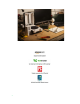
Inside the Box Thank you for purchasing the Matter and Form 3D Scanner. Included in your box, you'll find: 1. One (1) Matter and Form 3D Scanner 2. One (1) AC Power Adapter 3. Four (4) Interchangeable Power Adapter Plugs (set of 4 international) 4. One (1) USB B Cable 5. One (1) Calibration Box or Card and stand 6. Set-up Manual 7. Electronics Documentation The scanner also features a removable plug in the center of the turntable bed.
Getting Started 9
Connecting the Scanner Once the scanner and accessories have been unboxed, the first step is to connect the scanner to your computer by following the connecting instructions in the Set-up Manual or the following: 1. Plug the USB Type A connector end into the computer; 2. Plug the USB Type B connector end into the scanner; 3. Connect the power cable to the scanner and plug the power cable into a surge protector; 4. Download the software from www.matterandform.net/download .
Using the Software From the Matter and Form software homepage, users can select to create a new scan, open recent scans, calibrate the scanner or open the scan viewer.
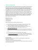
Calibrating the Scanner Calibrating the scanner may be the single most important step to take in order to get good results. Calibrating your scanner on a regular basis ensures that you get the most accurate results from your scan. To calibrate: 1. Make sure your scanner is connected to your computer and powered on. 2. Open the Matter and Form scanner software. 3. There are three options on the left on the start screen. Click "Calibrate" to start the calibration process. On Windows: On Mac: 4.
6. The scanner will rotate the calibration card (or box) left and right on the turntable, firing its lasers and collecting a range of data. Please be patient. This process can take several minutes. 7. Once the first step of calibration is done, follow the instructions for Calibration Step 2 and move the calibration card (or box) forward or back. Click "Continue Calibration" when the card (or box) is in its new position. 8. The scanner will rotate and fire its lasers again.
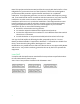
9. If your calibration is interrupted or fails, an error message should appear. Here are a few examples of the possible error messages one could see: If you receive any of the above Calibration Failed messages, try the action suggested in the message and try to calibrate again. If a step in calibration takes longer than 30 minutes, stop the calibration and try again or contact support@matterandform.net for tips and assistance. 10.
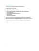
Preparing to Scan in Windows 1. Click on “New Scan” to begin. 2. Select Object Color Options - The software will now give you a choice of object color options: Single-Colored, Multi-Colored or Advanced. Single-Colored and Multi-Colored are both automatic settings while Advanced opens manual controls. Most users will find that the automatic settings of the scanner are more than adequate for their scanning purposes.
To figure out whether one should pick the Single-Colored or Multi-Colored option, use the following chart: 16
3. Click on your selection. 4. The scan viewer screen will open. Place your object on the scanner bed. 5. Click the “Scan” button, located at the top left. If you selected “Single-Colored”, the scanner will now tune for lighting, object shape and object color. Skip to Step 10.
If you selected “Multi-Colored”, the Scan Viewer will show you the camera feed of the scanner bed. The laser that tunes for lighter colors and the red spectrum colors of the color wheel will flash on. 6. Looking at the camera feed, position the object so that the laser line passes over the lighter colored area by using the Rotate Right or Rotate Left buttons provided on screen or moving the object by hand. 7. Click “Confirm Lightest Color”.
Preparing to Scan in Mac 1. To perform a simple scan place an object on the scanner bed and, from the Home screen, click on either Auto Scan or Manual Scan. Auto Scan is an automatic setting where the software detects the ideal camera exposure and the amount the bed moves as it rotates. Manual Scan allows users to customize settings. Use when scanning objects that have contrasting colors, or objects that are complex in shape or when scanning in complex lighting conditions.
If the object can be Auto Scanned, the scanner will determine optimal exposure. Skip to Step 9. If the object has contrasting colors, continue below. Clicking on Manual Scan also gives Mac users access to Advanced settings. More information on Advanced settings can be found in Advanced Scanning (p. ). 2. The Manual Scan window will open.
4. Line up your object on the bed so that the contrasting colors on the object are being hit by the lasers. This example uses a toy penguin. The lasers will be only capture the dark side of the penguin. Better but not enough of the black parts of the penguin are being hit by the laser as you can see in the windows above showing laser 1 and laser 2. Ideal placement. One laser is hitting mostly black and the other laser is hitting mostly white.
5. Once the object is placed ideally, click “Auto Tune”. 6. The Auto Tuning window will open. 7. Once Auto Tuning is finished, click “Start”. 8. The scanner head will move into position. 9. The scanning window will open and scanning will start.
10. If you wish to stop the scan for whatever reason, click “Pause” near the progress bar. You will have the option to resume scanning or finish the scan with an option to save the scan or not. Rotating, Zooming In and Panning Users can rotate, zoom in or move the scan on the screen (i.e. pan) to get a better view. These controls are available anytime and do not affect the scan in progress. To SPIN your model: Click and drag anywhere in the view window to rotate your model.
Doing More with the Scanner 24
Saving and Exporting a Scan Once the scan has completed, users will be prompted to save the finished, rough scan. We recommend that users save their rough scans before exporting to a different file format or cleaning. For more information on how to clean a scan, see “Cleaning a Scan” (p. ) To save as a .MFCX file: 1. Click “Save Now”. 2. Enter file name. 3. Click “Save”. To export the scan in a different file format: 1.
2. Select the file format you wish to export as; 3. Enter the file name for the new export; 4. Click “Save”. For additional information on the 3D file formats available, go to File Format Information (p. ) Cleaning a Scan During scanning, the scanner can sometimes pick up and add unintended points to the scan. The cause of these points can be reflections off the surface of the object or captured background movement, objects or reflections, amongst other things.
1. Click the "Clean" button on the tool bar. 2. Clean tools will appear in the area on the right. There are three major options: Crop Points, Brush Cleaning and Fuzzy Points/Auto Clean. There is also an “Undo” button to restore points that you have cleaned. 3. Cropping removes all points outside an area you specify. Use the sliders (click and drag or use your arrow buttons) to control how much of the image you want to crop out. Points will highlight in red when they are in the cut off area.
Points to be removed are highlighted in red. Result after clicking “Delete Selected Points” 4. Use the second slider to crop points away from the center. Slider has been moved to crop points outside the “cage” surrounding the vase.
Results after clicking “Delete Selected Points”. 5. Zooming into the vase, we can see that there are still a few unwanted points. The Brush Cleaning feature can remove these individual points. 6. Under “Brush Cleaning”, there is an option to adjust brush size and three function buttons. The button on the right activates the brush, the center button returns the mouse to regular mouse functions so the image can be rotated/zoomed and the left button deselects points previously highlighted.
Before: Unwanted points individually highlighted After: Unwanted points deleted 8. Zoom in close to remove even more points. Before: Note the points near the outer left surface. After: Points have been deleted. 9. All points can be removed including good points. Highlighting a section will remove all points in the path of the highlighted section. Rotate the model to make sure only unwanted points are highlighted. Example: Good portion of the vase has been highlighted with the brush tool.
Rotating the vase reveals holes on both sides. Click “Undo” to reverse unwanted changes or over-aggressive cleaning. 10. Another option is to use “Auto Clean”. The software automatically "cleans" what it determines are outlier points. Radius refers to the number of points surrounding each evaluated point in a scan. Threshold refers to the minimum distance, in millimetres, from the surrounding radius points that a potential outlier point must be for it to be cleaned/discarded.
The default values (Radius: 3, Threshold: 2.0) were used to clean the above example scan. Cropping tools can be used to clean the bed away. 11. Once cleaning has been finished, click the green “x” next to Clean and Crop to close out of “Clean”. A new message window will appear: 12. Congratulations! You have a cleaned scan. You are ready to save or export to a different file format. Cleaning Scans in Mac Below is an example of a raw scan of a toy taxi cab.
To get rid of these unwanted points, the software has a “Clean” function. 1. Click the "Clean" button on the tool bar. 2. Clean tools will appear on the right. There are four cleaning categories: Auto Clean, Layers, Cropping and Brush Cleaning. Auto Clean Clicking on the Auto Clean button reveals three Auto Clean settings: Light, Medium and Heavy.
Light cleaning – errant points still remain on the scanner bed and around the bumper. Medium cleaning – a few more points have been cleaned away. Heavy cleaning – errant points on the scanner bed are gone but so are some good points around the front wheel. Layers Clicking on Layers will open all the separate layers captured by each laser. Each layer represents a pass or full rotation. Clicking on the layer will select or un-select the layer from view.
Layer 1 only Layer 3 only Layer 6 only Cropping Clicking on the Cropping button opens crop tools. Users have the option of cropping from the top down, from the bottom up and from the center out. Values are in millimeters (mm) and are relative to the zero on the bed.
Example of top down cropping (all points removed above 38 mm from base) Example of bottom up cropping (all points removed below 24.7 mm from base) Example of center out cropping (all points removed in a radius of 31.6 mm from center) Brush Cleaning Clicking on Brush Cleaning opens instructions on how to transform your mouse into a brush or eraser tool that you can use to erase or fill in points.
Using ctrl-mouse, unwanted points are highlighted. Points are removed after clicking the “Delete Points” button. All points can be removed including good points. Highlighting a section will remove all points in the path of the highlighted section. Rotate the model to make sure only unwanted points are highlighted. After clicking the “Delete Points” button. If you know that wrong points are selected, click “Clear Selection” to un-select.
● Reset will undo any changes you’ve made but keep Clean functions open. ● Cancel Changes will cancel your changes and exit you out of cleaning. ● Apply Changes will save the changes you made and exit you out of cleaning. Save your cleaned scan as an MFCX file and/or export to a different file format.
Combining Scans The software allows you to join two separate scans into one 3D file with the help of the Combine tool in Windows and Align tool in Mac. This is a helpful tool for instances where features of an object have been missed because of the scanning angle. For example, in the previous section with the vase, features on the bottom and top of the vase were missed. By performing another scan at a different angle (i.e.
1. Open an existing and cleaned MFCX file. This file is your base file and should be the orientation you want your finished 3D file to be. It is also a good idea to ensure this is file with the most detail. 2. Click “Combine” in Windows or “Align” in Mac. Windows: Mac: 3. A message window will appear prompting you to choose a file to combine with. 4. Click “Choose File” to select the cleaned file you’d like to combine with. 5. Click “Open”. The automatic combining process will begin.
6. When the combining bar disappears, the combining process is complete. The two scans are now combined. In our sample, the vase now has a fully captured bottom and top. Note the crisscrossing rows of points indicating where the two scans have overlapped in this zoomed in image. 7. Save and/or export the combined scan with a different file name. The combining process can be repeated by adding additional scans to already combined files.
The Basics of 3D Scanning 42
How Our 3D Scanner Works The Matter and Form 3D Scanner is a laser-based scanner. Laser scanners work by shining a laser at an object, using a camera to capture data that is returned from the laser hitting the surface of an object and then using software to stitch all that data together. On the Matter and Form scanner, as the lasers pass over the surface of an object, data is generated at a rate of approximately 2,000 points per second.
During the scan, the bed will rotate forward, but will also sometimes rotate back. This is by design and is called Adaptive Scanning. Its purpose is to capture as much of the object as is physically possible. As new sets of points are captured, the distance between them and the previously-captured set of points is calculated.
that the choice can be a little less black and white. For example, objects that have colors on both sides of the wheel, but are very light, can often be successfully scanned with the Single-Color option. The closer a color gets to white the more it starts to have in common with other colors which are also close to white, and the fact that they’re on opposite sides of the wheel matters less. The same holds true for colors that are very dark (close to black).
3D Scanner Terms 46
File Format Information Besides our MFCX file format, there are several other file formats that all have unique attributes and can be used for a variety of purposes: FILE TYPE MFCX (project file) XYZ (point cloud) PLY (point cloud) OBJ (meshed) STL (meshed) 47 DESCRIPTION Matter and Form Inc’s proprietary file format that is the quickest and easiest format to use while utilizing Matter and Form’s software.
Point Cloud Basics A point cloud is a set of data points in a coordinate system. In a three-dimensional coordinate system, these points represent the external surface of an object and are usually defined by X, Y, and Z coordinates. There are five essential terms that are used to describe elements of a given point cloud: vertices, edges, faces, polygons and surfaces. Vertices A vertex is a position. It includes additional information such as color, normal vector, and texture coordinates.
Octree, Degree & Samples Per Node When you’re in the Windows version of the Matter and Form scanner software and saving or exporting your scan as a meshed object (i.e. as an OBJ or STL file), you are prompted to enter in your desired “Octree” and “Degree” settings. When you’re in the Mac version of the software, you are prompted to enter in your desired “Octree” and “Samples per node”.
For Windows - Degree : Each Octree cube has a collection of points. To make a mesh, each section needs to have a curve or line drawn through it using the points as reference. The polynomial degree tells the computer what type of line to draw through those points.
So how to choose your settings? Higher values for octree depth results in more detailed results. However, if you have a noisy scan, the software may not be able to distinguish what is a good point from a stray point and may attempt to treat them equally. This is where the samples per node value can help since it will limit or expand the number of points being considered.
Advanced Scanning 52
Introduction Advanced scanning grew out of the research and development we conducted when we were building the scanner software. We needed a way to control the fundamental aspects of the scanner and visualize the results, so we could understand what worked and what didn’t. The main screen scanning options - “Single-Colored” and “Multi-Colored” - both codify and encapsulate the knowledge we gained through using the advanced features.
Cam Feed Tab The Cam Feed tab shows what the camera is seeing. At the bottom there is a checkbox “Throttle Camera Feed (Use during scanning on a slow computer)”. When this is checked, only one in four images from the camera actually get displayed; the others are discarded in order to lower CPU usage. It doesn’t affect the scan. However, if you have a very slow computer, keeping this checked to reduce the strain on the CPU is a good idea.
nearly solid line), you’ve found the exposure that will give you the best scan results for the object. Manual Control Tab Manual Control tab w/ Color Detection tab selected Manual Control tab w/ Laser Detection tab selected The Manual Control tab is where you pick the camera exposure for capturing the color of the object, and for capturing the laser lines.
Color Detection The goal of Color Capture Exposure is to find the exposure where the object’s colors appear realistically. You want an exposure that shows the Colors on the object in a bright but not overexposed manner. Move the slider left or right to see the result in the Cam Feed. On the next two pages, examples will be given on what to look for when manually adjusting color settings.
Example 1: Picking the best exposure for color Here are three examples of color capture adjustments. As you can see in the images below, the second one is the best choice. It’s bright, but not so bright that it’s white. The color capture on a scan with this exposure will result in a fairly dark object. White looks grey. This is a good choice for color. This is overexposed.
Example 2: When the choice isn’t clear Sometimes you might find that the difference between two exposures doesn’t give you a strong impression about which is the better choice for color. There isn’t necessarily a wrong choice in this instance, either one will probably be OK. We recommend that a good way to help decide is to look at the white area of the scanner that holds the scanner bed (seen at the bottom of the Cam Feed screen). In which of the exposures does it appear clearest? Choose that one.
Laser Detection The exposure of the camera has major ramifications on the quality of the final scan. The basic rule is that the dark-colored areas of the object will need a bright camera exposure and the light-colored areas of the object will need a dark camera exposure in order to best detect laser lines firing at the surface of the object. The Laser Detection tab has two sliders, and one checkbox. The top slider (called Laser Detection Exposure) is used to set the primary laser exposure.
Example 3: Picking the Best Laser Exposure The best exposure in this set of images is the middle one. You have a nice solid line, with no gaps, and no dotted line effect. In this image the two laser lines have gaps in the middle. This is an area where the software is not able to pick out the laser in the image. Here the gaps are closed. This is a good set of laser lines.
Here, the laser line on the left is starting to disintegrate. It looks more like a dotted line than a solid line.
High Contrast Scanning High Contrast Scanning is a method that we developed in order to capture the best data possible when scanning objects that had more than one color present. During development, we discovered that black and white objects or objects with contrasting colors were difficult to scan. Exposure tuning for one color would mean that areas on the opposite end of the spectrum would scan poorly or not at all.
How Do I Identify High Contrast Objects? Example 5: Setting High Contrast Laser Detection Exposure Some models cannot be scanned with only one laser exposure. A great example is these little blocks of clay. The bottom one is white, the middle is blue, the top grey. Let’s take a look at the laser lines found at some different exposures. High contrast colors: grey and white both contrast with blue.
Here you can see the laser lines when a darker exposure is selected. The white and grey blocks show nice lines, but the blue isn’t there. Here you can see the laser lines when a lighter exposure is selected. The white and grey blocks don’t show up, but the blue block has a nice laser line. The Best of Two Exposures To solve the problem in example 5, we must use High Contrast Scanning. It provides the means to combine the best laser detection from two exposures, so you can capture more of the object.
1. Under the Manual Control tab, click on the Laser Detection tab to start the laser detection process. 2. Adjust the top Laser Detection Exposure slider to capture clean laser lines on the light areas of the object. When you’re satisfied that you’ve got the best lines possible, proceed to step 3. 3. Check the Enable High Contrast Scanning checkbox, which enables the bottom Laser Detection Exposure Two slider. 4.
Scanner Tab This tab contains a checkbox labelled “Enable Movement Override”. When checked, two sliders are enabled, “Bed Resolution” and “Head Step Resolution”. These sliders allow you to specify the degree of bed rotation and the number of millimeters the head will move during the manual scan process, overriding the automatic settings built into the software. Bed Resolution The larger the degree of bed rotation, the faster your scan will go, and the less detail you will capture.
set of points. If there is a large distance between the two sets of points, the bed will rotate back and capture data between the two sets of points. This helps ensure that as much of the model is captured as is physically possible. Changing the bed rotation degree size overrides Adaptive Scanning. Rotation will be fixed at whatever degree you have set it for.
Advanced Scanning for Mac Preferences In the “Scan” menu, click on Preferences to access crash reporting, check for updates and enable exporting under the General Tab. Under Viewer, point size and background color options can be changed. Manual Scan Settings Clicking on “Manual Scan” from the home page reveals manual settings screen. There are four small screens visible above the main screen. Rolling a mouse over the screens reveals what the screens are.
On the right side of the screen is a scrollable pane that contains all the manual controls for the scanner. Camera Exposure Camera exposure options include Color Exposure, White Balance, Laser Exposure (Laser 1, Laser 2, High Contrast Laser 1 Alternate and High Contrast Laser 2 Alternate). Color Exposure Move the slider to capture the best exposure for color quality. ● You want it bright enough to see the colors clearly but not too bright and over-exposed.
White balance setting is too cool giving the image a blue hue. White balance is set at a good setting for the room. The white of the calibration box looks neutral and close to what it actually looks like. White balance setting is too warm giving the object a slight yellow hue.
As previously described in Laser Detection (p. ), laser exposure refers to settings that affect the quality of the laser line detected. The goal is to have straight, clean laser lines. Setting the Lasers As you move the slider for Laser 1, you’ll notice that Laser 2 Exposure is tied to Laser 1. Clicking on the padlock icon unlocks Laser 2 Exposure for fine-tuning.
In the Combined Results view, we can see that the laser lines are dull, fuzzy and Laser 2 is barely visible. The exposure is likely too low. Moving the Laser 1 Exposure slider far in the other direction results in brighter but fuzzier lines with a lot of gaps. With Laser 2 locked, the slider is moved to find the best exposure.
Setting the Lasers – Con’t If you have an item that has contrasting colors or is black and white, click on the “Enable High Contrast Scanning” option. This will open up Laser 1 and 2 Alternate Exposure and add two additional preview screens to the top of the page. Open the view that isolates each laser by clicking on the preview screen at the top of the page. With the view in the main viewer, move the slider for that laser until you find the cleanest line.
This might be what one might see in the Combined Results screen when in Manual Scan. The yellow and pink blocks are showing up but the green block is not. Adjusting the main Lasers 1 and 2 gives clearer results. Laser 2 is unlocked to get the best results. Alternate Laser 1 and 2 have now been adjusted so that the green paper block can be scanned by the scanner.
Here’s a screenshot of the Laser Exposure settings to get a sense of the range of values necessary to achieve the results above. Settings window A Note About Exposures If a user uses both Mac and Windows software, he or she will notice that exposure values are expressed in different ways on the two different platforms. The table below offers a translation of the differences. The exposures run in the range of 2 to 2500, where 2500 is the brighter and 2 is the darker exposure.
Bed Rotation Scrolling down past Laser Exposures reveals Bed Rotation options. The default setting has adaptive scanning enabled. Adaptive Scanning is an automatic process whereby each new set of points is reviewed to determine: 1) how far the model has rotated since the previous set of points and, 2) the number of points captured.
Troubleshooting 77
Introduction We will say this upfront… bad scans can happen. Anyone who has spent time scanning objects with a 3D scanner knows the frustration of setting up a scan, waiting for it to finish and then coming back when it’s done only to find that there are giant holes of missing data or the object has fallen over mid scan. These setbacks can be overcome, however, if we keep in mind a few key principles.
Bad Lighting Proper lighting plays a key role in producing quality scans. Insufficient or improper lighting directly affects the data that the scanner picks up from the object. To illustrate this point, we scanned a Red Delicious apple under different lighting conditions. For detailed information on proper lighting, see The Importance of Lighting (p. 45). Scan Result Lighting Condition Too Bright 12” from a window on a bright, sunny day Note the gaps in the surface of the scan.
By keeping in mind the optimal lighting condition discussed in The Importance of Lighting (p. 45), we can produce much better scans of the exact same object, as seen on the next page.
Calibration Ensuring your scanner is properly calibrated has a tremendous impact on your scan’s geometric accuracy. Failure to calibrate directly impairs the accuracy of the scanned object’s point cloud as it is being constructed, distorting the final scan. The solution is to calibrate and recalibrate as needed. Even a small movement in the scanner’s placement can affect its calibration and, consequently, its precision.
Inadequate Exposure and/or Missing Points Objects that have stark, contrasting colors necessitate different camera exposures and might prove difficult during automatic “tuning.” Tuning is the process by which the software determines the best camera exposure for capturing the color of the object and the best exposure for capturing where the laser is hitting the object. Repositioning the object on the turntable so the camera can tune to a different side of the object might resolve this problem.
Errant Points and/or Background Noise The scanner was designed with busy workplaces in mind: people walking by workspaces while scanning is underway, conversations happening over desks where scanners are working. A defining component and feature of our scanner is its “cleaning” functions that enable users to erase unwanted points. (See Cleaning a Scan (p. ) for more detail on how to clean.
Black or Missing Scans On occasion, users have started to scan an object only to have the object turn into a solid black mass and/or a single black dot. A vase converted into a black mass during scanning. A vase converted into a single black dot during scanning These problems are typically a result of the user’s computer not having enough memory or capacity to process the scan and mesh correctly, or because there is an issue with the graphics card driver.
5. Find the line “”. The number is the number points the software will display. The default is 3.5 million points. 6. Change “3500000” to a lower number (i.e. “1500000”. The range of usable display information is from a low of 1 million points (1000000) to a high of 5 million points (5000000). 7. Save the changes to the file, close the Config file and relaunch the MF software. 8. Open your point cloud files, mesh and combine using the new settings.
Copyright © 2015 Matter and Form Inc. Matter and Form and the MF logo are trademarks of Matter and Form Inc. All rights reserved. No part of this publication may be reproduced in any form without the written permission of Matter and Form Inc.