
Installation Guide


9
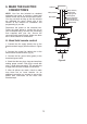
Figure 13
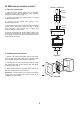
Figure 14
9. ATTACHING THE
MOUNTING PLATE
Step 1. Remove the 1 of 3 screws from the
mounting ring and keep it for future use. Loosen
the other 2 screws. (Do not remove)
Step 2. Place the key holes on the mounting plate
over the 2 screws previously loosened from the
mounting ring, turn mounting plate until it locks in
place at the narrow section of the key holes.
Secure by tightening the 2 screws previously
loosened and the one previously removed. (Fig. 13)
10. INSTALLING THE LIGHT
KIT
REMEMBER: To disconnect the power.
If you do not plan to install the light
kit with your fan at this time, skip
step 1, 2, 3 & 4.
1. Remove 1 of 3 screws from the mounting plate
and loosen the other 2 screws. (Do not remove)
2. Raise and hold the LED light kit close to the
mounting plate and proceed to do the wire
connections. Make the 2-pin wire connections:
(Fig. 14)
- Red to white
- Black to black
3. Place the key holes from the light kit over the 2
screws previously loosened from the mounting
plate, turn the light kit until it locks in place at the
narrow section of the key holes. Secure by
tightening the 2 screws previously loosened and
the one previously removed. (Fig. 14)
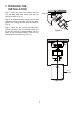
4. Raise the glass shade assembly up against the
mounting plate. The three slots inside the
mounting plate should be placed against the three
studs on the glass shade assembly, and secure it
to the mounting plate until snug.
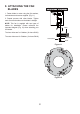
5. If installing the optional metal light cover, make
sure is securely tighten.
NOTE: The metal light cover included with your
fan is an option to replace the glass for the light in
the event that you prefer not to use the light
feature of your fan. The metal light cover is not
necessary for the light operation; it can be saved
for later use if desired.
Screws
Mounting ring
Mounting
plate
Glass shade
assembly
LED light kit
Connectors
Screws
studs
Slots
Mounting plate
Metal light
cover