
Installation Guide

4
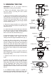
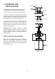
Figure 6
Figure 5
Ceiling
hanger
bracket
Ceiling
canopy
Canopy
cover
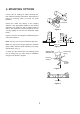
5. HANGING THE FAN
REMEMBER to turn off the power. Follow the
steps below to hang your fan properly.
1. Remove the decorative canopy bottom cover
from the canopy by turning the cover counter
clockwise. (Fig. 5)
2. Remove the hanger bracket from the canopy by
removing the 1 of 2 screws from the bottom of the
hanger bracket and loosening the other one a half
turn from the screw head. Next, turn the canopy
counter clockwise to removing the hanger bracket
from the canopy. (Fig. 5)
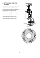
3. Secure the hanger bracket to the ceiling outlet
box using screws and washers included with your
outlet box. (Fig. 6)
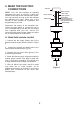
4. Loosen the two set screws and remove the hitch
pin and lock pin from the central shaft/top coupling
of the motor assembly. Doing so will allow the
down rod to enter the central shaft. (Fig. 7)
5. Route wires exiting from the top of the fan motor
through the coupling cover, canopy cover and
canopy and then through the ball/downrod. (Fig. 7)
6. Align the holes at the bottom of the downrod
with the holes in the collar on top of the motor
housing. Carefully insert the hitch pin through the
holes in the collar and downrod. Be careful not to
jam the pin against the wiring inside the downrod.
Insert the lock pin through the hole near the end of
the hitch pin until it snaps into its locked position.
(Fig. 7)
Warning/Caution: Failure to properly install lock
pin as noted in step 6 could result in fan loosening
and possibly falling.
7. Tighten two set screws on top of the fan motor
firmly.
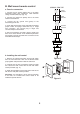
8. Now lift the motor assembly into position and
place the hanger ball into the hanger bracket.
Rotate down rod until the "Check Tab" has dropped
into the "Registration Slot" and the down rod and
ball assembly seat firmly. The down rod and ball
assembly should not rotate if this is done correctly.
(Fig. 8)
9. An additional safety support is provided to
prevent the fan from falling. Secure the safety cable
to the ceiling joist with screw and washer. (Fig. 8)
Figure 7
Figure 8
Tab
Mounting screws
(supplied with
electrical box)
UL Listed
electrical
box
Hanger bracket
Supply wires
Downrod
Coupling cover
Canopy
Canopy cover
Set screws
Hitch pin
Lock pin
Registration
slot
Screw
Safety cable