
Installation Sheet

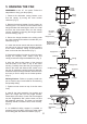

6
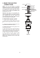
B. Wall mount remote control
a. Wall control wire connection
1. Connect the wall control supply (black) wire to
the black household supply wire as shown in
Figure 10.
2. Connect the wall control (black) wire to the
white neutral household wire. (Fig. 10)
3. Connect the wall control ground wire (green) to
the household ground wire.
4. If your wall outlet box has a ground wire (green
or bare copper), connect the wall control's
yellow/green ground wire to it; otherwise connect
the wall control's yellow/green ground wire directly
to one of the screws from the wall outlet box.
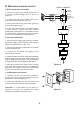
b. Fan wire connection
1. Connect the fan supply (black) wire to the black
household supply wire (Conductor cable between
ceiling and wall outlet box). (Fig. 101)
2. Connect the neutral fan (white) wire to the white
neutral household wire.
3. Connect the fan ground wire (green) to the
household ground wire.
4. Check that the two plugs, large and small are
making proper contact. One plug is small with
only a single wire connection. The second plug
is larger and connects multiple colored wires.
5. After all connections are made, check to make
sure there are no loose strands. As an additional
precaution we suggest to secure the plastic wire
connectors to the wires with electrical tape.
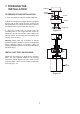
c. Installing the wall control
1. Carefully tuck the wire connections inside the
junction box. Secure the wall control with the two
wall switch screws provided. (Fig. 11)
2. Attach the wall plate over the wall control and
secure with the two wall plate screws provided.
Disclaimer: If a wall switch is to be used, for
warranty to be valid, our included wall control
needs to be installed to operate this fan.
Figure 10
Figure 11
SUPPLY CIRCUIT
BLACK
Ground
Conductor
Ceiling
Outlet Box
Green Ground
Lead
Ground to
Downrod
GREEN
WHITE WHITE
BLACKBLACK
BLACK BLACK
BLACK