Super Janet 60”, 52" or 42" CEILING FAN READ AND SAVE THESE INSTRUCTIONS FAN RATING AC 120V. 60Hz FOR DAMP LOCATION Please do not use any electric or battery powered tools in the assembly and installation of this or any Matthews Fan Company product.
TABLE OF CONTENTS Tools and Materials Required.........................................................................................1 Package Contents ......................................................................................................... 1 Safety Rules................................................................................................................... 2 Mounting Options........................................................................................................
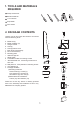
1. TOOLS AND MATERIALS REQUIRED Philips screwdriver Blade screwdriver 11 mm wrench Step ladder Wire cutters 2. PACKAGE CONTENTS f Unpack your fan and check the contents. You should have the following items: g a. b. c. d. e. f. g. h. i. j. k. l. Blade set (3) Blade medallion (3) Hanger bracket Canopy Canopy bottom cover Ball / down rod assembly Fan motor assembly Mounting plate 18W LED light kit Glass shade Transmitter+holder+2 mounting screws Wall transmitter incl. 2 mounting screws and 3 wire nuts m.
3. SAFETY RULES 1. To reduce the risk of electric shock, insure electricity has been turned off at the circuit breaker or fuse box before beginning. 8. To avoid personal injury or damage to the fan and other items, be cautious when working around or cleaning the fan. 2. All wiring must be in accordance with the National Electrical Code and local electrical codes. Electrical installation should be performed by a qualified licensed electrician. 9.
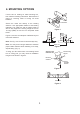
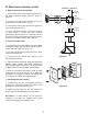
4. MOUNTING OPTIONS If there isn't an existing UL listed mounting box, then read the following instructions. Disconnect the power by removing fuses or turning off circuit breakers. Outlet box Secure the outlet box directly to the building structure. Use appropriate fasteners and building materials. The outlet box and its support must be able to fully support the moving weight of the fan 15.9 kgs (35lbs) or less. Do not use plastic outlet boxes.
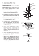
5. HANGING THE FAN Screws Before touching a screw driver thoroughly read these instructions. Metal plate Warning/Caution: Before installing fan, turn off power at service panel and check all visible screws and bolts for tightness. Coupling cover 1. Remove the metal plate and coupling cover from the fan motor by removing the two screws from the rim of metal plate. (Fig. 5) Collar Fan motor 2. Secure the hanger bracket to the ceiling outlet box using screws and washers included with your outlet box.
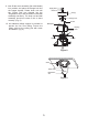
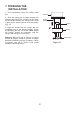
9. Now lift the motor assembly (fan with blades) into position and place the hanger ball into the hanger bracket. Rotate down rod until the "Check Tab" has dropped into the "Registration Slot" and the down rod and ball assembly seat firmly. The down rod and ball assembly should not rotate if this is done correctly. (Fig. 9) Supply wires Downrod Canopy Canopy cover Screws Metal plate 10. An additional safety support is provided to prevent the fan from falling.
6. MAKE THE ELECTRIC CONNECTIONS NOTE: Your fan has included as standard equipment two types of controls: a hand held remote control and a wall mounted wall control. You may use both as long as the dip switches are calibrated the same. Select one of the controls at this moment for installation and programming of your fan. Outlet box White ("AC IN N") Green or bare copper (ground) Black ("AC IN L") Black (motor) Disconnect the power at the electrical box.
B. Wall mount remote control BLACK 1. Connect the wall control supply (black) wire to the black household supply wire as shown in Figure 11. BLACK BLACK BLACK 3. Connect the wall control ground wire (green) to the household ground wire. 4. If your wall outlet box has a ground wire (green or bare copper), connect the wall control's yellow/green ground wire to it; otherwise connect the wall control's yellow/green ground wire directly to one of the screws from the wall outlet box. b.
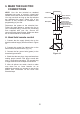
7. FINISHING THE INSTALLATION 1. Tuck connections neatly into ceiling outlet box. Outlet box 2. Slide the canopy up to hanger bracket and place the key hole on the canopy over the screw on the hanger bracket, turn canopy until it locks in place at the narrow section of the key holes. (Fig. 13) Hanger bracket Screws 3. Align the circular hole on canopy with the remaining hole on the hanger bracket, secure by tightening the two set screws.
8. ATTACHING THE FAN BLADES 1. Fasten the blades to the blade arms and blade medallion using the blade attachment screws and fiber washers. Start a screw with fiber washer into the blade medallion, but do not tighten. (Fig. 14) Screw Fiber washer 2. Repeat for the remaining blade attachment screws and fiber washers. Tighten each screw securely starting with the center screw. Make sure the blade is straight. Blade medallion Fan 3. Repeat these steps for the remaining blades.
10. INSTALLING THE LED LIGHT KIT AND GLASS SHADE 1. Remove 1 of 3 screws from the mounting plate and loosen the other 2 screws. (Do not remove) 2. Raise and hold the LED light kit close to the mounting plate and proceed to do the wire connections. Make the 2-pin wire connections: (Fig. 16) - White to white - Blue to black 3. Place the key holes from the LED light kit over the 2 screws previously loosened from the mounting plate, turn light kit until it locks in place at the narrow section of the key holes.
11. PROGRAMMING YOUR FAN AND OPERATING THE REMOTE CONTROL AND WALL CONTROL ON D ON ECE D ON Before programming takes place, fan must be fully assembled and mounted to the ceiling with blades attached. You must also choose which control you will be using for programming the fan, the remote or the wall control. No other wall control should be used with this fan but that which was included. Using another wall control other than ours will damage your fan and void your warranty.
NOTE: If the self calibration test failed, turn the AC power off; restore power and process the self calibration test again. NOTE: During self calibration test, the remote and the wall control are non-functional. NOTE: The learning frequency function and calibration test will continue to retain the last frequency and calibration set even when the power is shut off. If the frequency is changed self calibration test will occur again. self set AC the F.
13 CARE OF YOUR FAN Here are some suggestions to help you maintain your fan 1. Because of the fan's natural movement, some connections may become loose. Check the support connections, brackets, and blade attachments twice a year. Make sure they are secure. (It is not necessary to remove fan from ceiling.) 2. Clean your fan periodically to help maintain its new appearance over the years. Use only a soft brush or lint-free cloth to avoid scratching the finish.
LIMITED LIFETIME WARRANTY MATTHEWS-GERBAR, LTD. DBA MATTHEWS FAN COMPANY LIFETIME LIMITED WARRANTY. Ceiling fans are warranted by Matthews-Gerbar, Ltd. to the original user against defects in workmanship or materials under normal use and inside installation for: Motors: Lifetime of original purchaser: Labor & Component parts: (lights, finish, blades, etc…): one year after date of purchase, Light Bulbs: no warranty. Any part, which is determined by Matthews-Gerbar, Ltd.