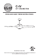
C-IV 60” CEILING FAN READ AND SAVE THESE INSTRUCTIONS FAN RATING AC 120V. 60Hz Please do not use any electric or battery powered tools in the assembly and installation of this or any Matthews Fan Company product.
TABLE OF CONTENTS Tools and Materials Required.........................................................................................1 Package Contents ......................................................................................................... 1 Safety Rules................................................................................................................... 2 Mounting Options........................................................................................................
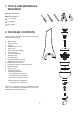
1. TOOLS AND MATERIALS REQUIRED Philips screwdriver Blade screwdriver 11 mm wrench Step ladder Wire cutters b 2. PACKAGE CONTENTS c d e Unpack your fan and check the contents. You should have the following items: a. b. c. d. e. f. g. h. i. j. k. l. m. n. o. p. q.
3. SAFETY RULES 1. To reduce the risk of electric shock, insure electricity has been turned off at the circuit breaker or fuse box before beginning. 8. To avoid personal injury or damage to the fan and other items, be cautious when working around or cleaning the fan. 2. All wiring must be in accordance with the National Electrical Code and local electrical codes. Electrical installation should be performed by a qualified licensed electrician. 9.
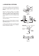
4. MOUNTING OPTIONS If there isn't an existing UL listed mounting box, then read the following instructions. Disconnect the power by removing fuses or turning off circuit breakers. Outlet box Secure the outlet box directly to the building structure. Use appropriate fasteners and building materials. The outlet box and its support must be able to fully support the moving weight of the fan 15.9 kgs (35lbs) or less. Do not use plastic outlet boxes.
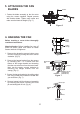
5. ATTACHING THE FAN BLADES Screws 1. Fasten the blade assembly to the fan motor using the screws supplied. Repeat process with another blade. Tighten each screw and make sure the blade is straight. (Fig. 5 ) Fan motor Blades Figure 5 6. HANGING THE FAN Ceiling hanger bracket Before touching a screw driver thoroughly read these instructions. Warning/Caution: Before installing fan, turn off power at service panel and check all visible screws and bolts for tightness. Ceiling canopy 1.
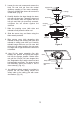
5. Loosen the two set screws and remove the hitch Pin and lock pin from the central shaft/top coupling of the motor assembly. Doing so will allow the down rod to enter the central shaft. (Fig. 9) Supply wires Downrod Canopy 6. Carefully feed the fan wires through the down rod and pull them taut. Thread the down rod into the central shaft and tighten with the lock pin and hitch pin previously removed, re-tighten the set screws against the downrod.
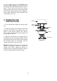
7. MAKE THE ELECTRIC CONNECTIONS Warning: The power should have already been disconnected. Follow the steps below to connect the fan to your household wiring. Use the wire nuts supplied with your fan. Secure the wire nuts with electrical tape. Make sure there are no loose strands or connections. NOTE: The Hand Held Remote Control units included with your ceiling fan are equipped with 16 code combinations to prevent possible interference from or to other remote units.
4. If your outlet box has a GROUND wire (Green or Bare Copper) connect this wire to the Hanger Ball and Hanger Bracket Ground wires. If your outlet box does not have a Ground Wire, then connect the Hanger Ball and Hanger Bracket Ground Wires together. Secure wire connection with the plastic wire nut provided. (Fig. 13) 8. FINISHING THE INSTALLATION Outlet box 1. Tuck connections neatly into ceiling outlet box. Hanger bracket Screws 2.
9. ATTACHING THE MOUNTING PLATE Step 1. Remove the 1 of 3 screws from the mounting ring and keep it for future use. Loosen the other 2 screws. (Do not remove) Step 2. Place the key holes on the mounting plate over the 2 screws previously loosened from the mounting ring, turn mounting plate until it locks in place at the narrow section of the key holes. Secure by tightening the 2 screws previously loosened and the one previously removed. (Figure 16) Mounting ring Mounting plate Screws Figure 16 10.
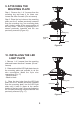
. INSTALLING THE DECORATIVE BOTTOM COVER 1. Raise decorative bottom housing up against bottom of fan housing and secure it to the fan by turning the decorative bottom cover clockwise until snug. DO NOT OVERTIGHTEN. (Fig. 18) NOTE: The additional metal light cover included with your fan is an option to replace the glass diffuser (assembled in the decorative bottom housing) in the event that you prefer not to use the light feature of your fan. (Fig.
. OPERATING THE REMOTE CONTROL Install 12V MN21/A23 battery (included). To prevent damage to transmitter, remove the battery if not used for long periods. (Fig. 20) Restore Power to Ceiling Fan. A. H, M, L Buttons: These buttons are used to set the fan speeds as follows; Figure 20 L: Low Speed M: Medium Speed H: High Speed B. OFF Button: This button turns the fan off. REV C. ACCESSORY Button: This button is used to turn on and off the light kit and also controls the brightness setting.
14. CARE OF YOUR FAN Here are some suggestions to help you maintain your fan 1. Because of the fan's natural movement, some connections may become loose. Check the support connections, brackets, and blade attachments twice a year. Make sure they are secure. (It is not necessary to remove fan from ceiling.) 2. Clean your fan periodically to help maintain its new appearance over the years. Use only a soft brush or lint-free cloth to avoid scratching the finish.