
Installation Guide


6
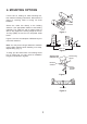
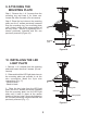
7. MAKE THE ELECTRIC
CONNECTIONS
Warning: The power should have already been
disconnected. Follow the steps below to
connect the fan to your household wiring. Use
the wire nuts supplied with your fan. Secure the
wire nuts with electrical tape. Make sure there
are no loose strands or connections.
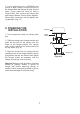
NOTE:
The Hand Held Remote Control units
included with your ceiling fan are equipped with
16 code combinations to prevent possible
interference from or to other remote units. The
frequency switches on your Receiver and
Transmitter units have been preset at the
factory. Please re-check to make sure the
switches on both units are set to the same
positions. The frequency settings should be
changed only in case of interference or if a
second or more remote controlled ceiling fans
are installed in the same room. Any code
combination will operate the ceiling fan and light
as long as the Receiver and Transmitter units
are set to the same codes (Fig. 11)
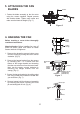
1. Insert Receiver into Hanger Bracket with the
flat side of the Receiver facing the ceiling. (Fig.
12)
2. Motor to Receiver Electrical Connections:
Connect the WHITE wire from the fan to the
WHITE wire marked "TO MOTOR N" from the
Receiver. Connect the BLACK wire from the fan
to the BLACK wire marked "TO MOTOR L" from
the Receiver. Proceed to secure all wire
connections with the plastic wire nuts provided.
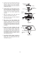
Connect the BLUE wire from the fan to the
BLUE wire marked "For Light" from the receiver.
Proceed to secure all wire connections with the
plastic wire nuts provided. (Fig. 13)
Note: Fan must be installed at a maximum
distance of 40 feet from the transmitting unit for
proper signal transmission between the
transmitting unit and the fan's receiving unit.
3. Receiver to House Supply Wires Electrical
Connections: Connect the WHITE wire (Neutral)
from the outlet box to the WHITE wire marked
"AC in N" from the receiver. Connect the BLACK
wire (Hot) from the outlet box to the BLACK wire
marked "AC in L" from the receiver. Secure all
wire connections with the plastic wire nuts
provided. (Fig. 13)
Figure 11
Figure 12
Figure 13
Receiver
Hanger
bracket
WHITE (NEUTRAL)
WHITE (NEUTRAL)
GREEN OR BARE
COPPER (GROUND)
WHITE ("AC IN N")
WHITE ("TO MOTOR N")
GROUND-
(GREEN)
(3 GROUND WIRES
ON CEILING FAN)
OUTLET BOX
BLACK (HOT)
BLACK ("AC IN L")
BLACK ("TO MOTOR L")
RECEIVER
BLACK (MOTOR)
BLUE (FOR LIGHT)
BLUE (FOR LIGHT)