
Owner's manual


Max Machinery, Inc. G Series User Manual © Copyright 2013 Rev. 001Q4
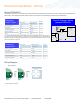
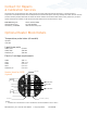
Analog
PCA label Mating Cable
Wire Color
Turck
Pin #
Case Ground Case Blue 3
Common Com Black 4
Power * V+ Brown 1
Signal Output (+) Sig Grey 5
Signal Output (-)** Ret White 2
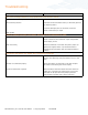
WARNING
Installation and removal should only be facilitated by trained personnel
Verify transmitter output type (ANALOG or FREQUENCY) before wiring, inappropriate wiring could
result in damaging the circuit.
Removal note: The transmitter does not need to be removed from the ow meter for any eld servicing or adjustments.
Normally, the ow meter and transmitter are shipped back to the factory for calibration or service as a unit. If the
transmitter needs to be removed from the ow meter for installation, be sure to retighten the transmitter snugly in
order to ensure proper sensor alignment.
Mechanical Installation
1. The transmitter is attached to the ow meter’s threaded magnet shield. Hand tighten only. (~ 3 ft-lb)
2. The transmitter lid has four thread paths. To realign the cable, remove the lid and rotate up to 180° and retighten
using an alternate starting point. Tighten to compress the O-ring seal.
Removal
1. Remove electrical connections
2. Unscrew transmitter, using a wrench if necessary.
Moisture Seal Protection
On all models, the housing is designed as a liquid and vapor-tight enclosure. There is an O—ring seal at the lid of the
housing — these need to be fully seated. A properly sealed transmitter will prevent the formation of damaging moisture
inside the housing.
Turck connector model: The connector is sealed to the lid at the factory and is ready for use.
NPT Model: To ensure a moisture-tight seal, apply appropriate sealant to the threads at installation.
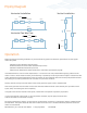
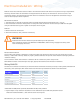
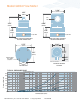
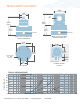
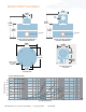
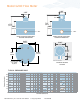
Wiring ANALOG
The electrical connector versions are pre-wired inside the transmitter and ready to accept a mating cable (available from
the factory). The liquid-tight, NPT models need to be wired during installation as shown in the table below:
*Model 29X-xxx-000, 24vdc powered, Model 29X-xxx-100, 12vdc powered
** Signal output is fully isolated: If attached to a true differential input a 10K Ohm pulldown resistor
should be installed between (—) and common at the receiving end.
Electrical Installation - Wiring