Manual CT60-IP & CT80-IP April 2009 CT60-IP / CT80-IP Ignition Protected Thruster With electronic thruster control CERTIFIED ISO 8846 INSTALLATION OPERATION MAINTENANCE Serial No.: -----------------------------------------------------Installation date: ------------------------------------------------- THIS MANUAL MUST BE KEPT ONBOARD AT ALL TIMES Max Power S.A.S, 10 allée François Coli, 06210 MANDELIEU, FRANCE Tél. +33 492 19 60 60 - Fax + 33 492 19 60 61 email : mp@max-power.com - www.max-power.
Manual CT60-IP & CT80-IP April 2009 Contents Section 1 2 3 4 5 6 7 8 9 10 11 12 13 14 15 16 17 18 19 20 21 22 23 24 25 26 Title General installation guidelines Tunnel Composite motor support and drive leg Electric Motor Propellers Protection grills Electrical installation Main power fuse Batteries Electronic control box Control panel and thruster control box functions Control panel installation Tests Electrical measurements Operation Alarms or thermal switch-off Safety Maintenance Electrical installation
Manual CT60-IP & CT80-IP April 2009 1.
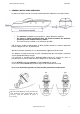
Manual CT60-IP & CT80-IP April 2009 2. TUNNEL Once the final tunnel position has been determined and all dimensions have been checked, mark the centre-point of the tunnel on both sides of the hull and drill holes of 8 –10 mm ∅ on either side. Using a metal rod, construct a compass with a 100mm radius. Insert through the holes and trace the ellipses, as shown below.
Manual CT60-IP & CT80-IP April 2009 DO NOT LAMINATE THE AREA OF THE TUNNEL TO WHICH THE ELECTRICAL MOTOR SUPPORT WILL BE FIXED. 3. COMPOSITE MOTOR SUPPORT AND DRIVE LEG For the CT60-IP (Mono): The propeller must be at the center of the tunnel. The motor support and the drive leg will therefore not be centered in the tunnel. For the CT80-IP (Duo): The motor support and the drive leg will be centered in the tunnel.
Manual CT60-IP & CT80-IP April 2009 positioning and then tightening the two 8mm ∅ screws alternatively using a 5.5mm Allen key (maximum torque: 25Nm). Check that the propellers rotate freely, without resistance or friction. It is imperative that the holes and the screws remain free of sealing compound, otherwise there is a risk of an incorrect assembly of the parts. Caution: do not use graphite grease.
Manual CT60-IP & CT80-IP April 2009 It is essential to install a manual battery isolator and if possible an electric battery isolator at the base of the thruster motor power line. When using a manual battery isolator it must be visible, clearly marked & easily accessible. Thruster motor power supply: These values are given as an indication, assuming that the batteries are charged at 100% and in charge, that is either 13.8V or 25.4V. The performance data of the CT60-IP / CT80-IP is measured with an approx.
Manual CT60-IP & CT80-IP April 2009 10. ELECTRONIC CONTROL BOX WARNING: The electronic controller must be positioned outside of the zone at risk in which there may be potentially flammable gases. Install a fused circuit breaker / switch in the boat's main DC distribution panel marked BOW THRUSTER. This circuit breaker / switch should ideally be supplied from a different battery bank to the one used for powering the thruster.
Manual CT60-IP & CT80-IP April 2009 12. CONTROL PANEL INSTALLATION Control panels should be protected from the natural elements while the thruster is not in use. Install the control panel(s) in easily accessible positions, without obstructing the main engine and/or steering controls. When fixing the panel with the stainless steel screws, make sure to install the pre-cut rubber seal, as supplied with the panel, ensuring that it is in the correct place.
Manual CT60-IP & CT80-IP April 2009 14. ELECTRICAL MEASUREMENTS In normal “usage” mode, i.e. thrusters running, boat in the water, with fully charged batteries under ongoing charge (alternator), electrical measurements should be made at the following points: At the batteries At the battery cut-off switch At the fuse At the electric motor’s connections At the power supply arriving at the thruster control box These measurements will enable you to detect voltage drop.
Manual CT60-IP & CT80-IP April 2009 17. SAFETY Switch off means to cut the power at both the DC equipment panel (control power supply) & the thruster battery isolator (thruster power supply) after having used the thruster. Under no circumstances should any flammable products be stored next to the electric components of the thruster. Care must be taken not to use the thruster in areas where there may be people swimming or in the water close to the thruster.
Manual CT60-IP & CT80-IP April 2009 19. ELECTRICAL INSTALLATION DIAGRAM www.max-power.
Manual CT60-IP & CT80-IP April 2009 20. RELAY AND CONTROL BOX CONNECTIONS www.max-power.
Manual CT60-IP & CT80-IP April 2009 21. SPARE PARTS DIAGRAM www.max-power.
Manual CT60-IP & CT80-IP April 2009 22.
Manual CT60-IP & CT80-IP April 2009 23. TROUBLESHOOTING GUIDE Before contacting your nearest Max Power distributor, please check the below troubleshooting guide.
Manual CT60-IP & CT80-IP April 2009 25. WARRANTY COVERAGE Introduction The purpose of this document is to set out the terms of warranty cover offered in relation to products purchased by the End User from Max Power or its approved network of resellers.
Manual CT60-IP & CT80-IP 4) April 2009 Warranty Terms If the material is used for anything other than for pleasure craft, the guarantee is limited to a six-month period. Year 1 All factory testing, diagnosis, repairs and replacements are performed at no charge to the End User. All parts and up to two hours of labour are covered for repairs and replacements conducted in the field. Year 2 All factory testing, diagnosis, repairs and replacements are performed at no charge to the End User.
Manual CT60-IP & CT80-IP April 2009 Serial No.: 26. WARANTY FORM VERY IMPORTANT: Please complete this form and fax a COPY to Max Power with a copy of the installation invoice or the invoice of the yacht/boat in order for the warranty to come into effect. To be completed by the owner: Name of owner: Tel.