
Manual

Manual CT60-IP & CT80-IP April 2009
www.max-power.com 1
Contents
Section
Title
Page
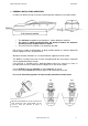
1 General installation guidelines 2
2 Tunnel 3
3 Composite motor support and drive leg 4
4 Electric Motor 5
5 Propellers 5
6 Protection grills 5
7 Electrical installation 5
8 Main power fuse 6
9 Batteries 6
10 Electronic control box 7
11 Control panel and thruster control box functions 7
12 Control panel installation 8
13 Tests 8
14 Electrical measurements 9
15 Operation 9
16 Alarms or thermal switch-off 9
17 Safety 10
18 Maintenance 10
19 Electrical installation diagram 11
20 Relay and control box connections diagram 12
21 Spare parts diagram 13
22 Spare parts list 14
23 Troubleshooting guide 15
24 Worldwide distribution network 15
25 Warranty coverage 16
26 Warranty form 18
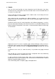
The use of qualified marine personnel, with experience in bow thruster installation, is
strongly advised. Where possible, the boat manufacturer’s design departments, architects,
and/or shipyards should be consulted, prior to installation taking place. For any boat requiring
official classification, bodies of approval should also be consulted at the earliest opportunity.
In any case, all other bodies, governmental or otherwise, should be contacted to ensure
conformity with legal regulations relating to the boat in question.
IT IS ESSENTIAL TO READ THE FOLLOWING MANUAL CAREFULLY
BEFORE INSTALLING THE THRUSTER
WARNING
Under no circumstances should the thruster casing be opened. Opening or modifying the
thruster may result in it no longer being Ignition Protected. In case of a problem please contact
your local Max Power distributor.
NB : The thruster is delivered without accessories (fuse, fuse holder, control panel).