R/C Aerobatic Sports Aircraft Assembly And Instruction Manual Copyright Century UK Limited 2021 www.centuryuk.
Warning: This radio controlled model is not a toy. It requires skill to fly and is not recommended for use by beginners without assistance from an experienced model pilot. It should not be operated by children without the supervision of a suitably experienced adult. Max-Thrust reserves the right to modify the specification of this model at any time. Safety Precautions 1. Do not attempt to repair or modify this aircraft with non-factory parts. 2.
Overview Thank you for purchasing this MAX-THRUST Ruckus radio controlled model aircraft. The Ruckus offers a stunning combination of terrific looks and sensational flight performance. Manufactured from “EPOFLEXY” it is extremely robust, however, in the event of a “less than perfect” arrival, we supply a range of spares to get you flying again in the shortest time.
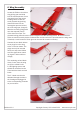
1. Undercarriage Fix the undercarriage in position with the four 2.6 x 12mm self-tapping screws as shown. If the screws become excessively tight whilst fixing, simply back them off a turn or two, and then continue. Note: The undercarriage legs are angled towards the front of the fuselage. 4 x 2.6 x 12mm Screw 2. Horizontal Tail-Plane Remove the moulded tab at the end of the fuselage with a sharp knife. Slide the horizontal tail-plane into the fuselage slot as shown.
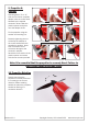
4. Tail-Plane Fixing Fix the horizontal tail-plane and vertical fin in position with the two 2.6 x 35mm screws provided. The screws must be tightened sufficiently to securely fix the parts in position, however be careful not to over-tighten the screws. 2 x 2.6 x 35mm Screw 5. Tail Control Horns Connect the rudder and elevator snap-links to their respective control horns as shown in images to the right.
. Wing Assembly Locate the 500mm aluminium wing joining spar and slide into the round aperture of one wing panel up to the centre locating collar. Locate the small plywood wing locking plate and insert into the rectangular aperture behind the main wing spar, (image G). Slide the remaining wing panel onto the exposed portion of the aluminium spar. The plywood locking plate will ensure perfect alignment of the two wing halves.
. Wing Fixing The moulded wing cowling is used to secure the wing to the fuselage and can only be fitted one way round. The cutout is towards the front on the aircraft. The longer screws are used at the front. 2 x M4 x 55mm Screw 1 x M4 x 38mm Screw The moulded wing cowling should be installed once the wing is in place and the cables are threaded though to the cockpit area. The wing and cowling can now be secured to the fuselage using the 3 M4 screws. 8.
9. Propeller & Spinner Following steps “1” to “9”, slide the aluminium propeller adaptor onto the motor shaft, followed by the tapered aluminium driver. Slide the plastic spinner back plate onto the adaptor shaft. 1 2 3 4 5 6 7 8 9 Fit the propeller using the washer and securing nut. Securely tightening the nut will clamp the adaptor to the motor shaft and fix the propeller in position. Note: Use of excessive force will cause damage to the aluminium adaptor.
11. Battery Installation The battery is mounted in to the model by removing the upper canopy that is held in place by magnets. Your flight battery, (not included in the PNP Version) can easily be installed and connected to the factory fitted “T” style connector. Make certain the battery is secured using the velcro straps and that the canopy is secure before flight. For added security of the battery pack we recommend using some self adhesive velcro applied to the battery and battery tray. 12.
MAX-T-RUCKUS-1 MAX-T-RUCKUS-2 MAX-T-RUCKUS-3 MAX-T-RIOT-4 MAX-T-RUCKUS-5 MAX-T-RUCKUS-6 MAX-T-RUCKUS-4 MAX-T-RIOT-10 MAX-T-RIOT-11 MAX-T-RIOT-12 MAX-T-RIOT-6-R MAX-T-RIOT-5 MAX-T-RIOT-7 MAX-T-RIOT-16 MAX-T-RIOT-8 MAX-T-RIOT-15 MAX-T-RIOT-14 Revision V1.1 Copyright Century UK Limited 2021 www.centuryuk.