Tech Note CAN bus components Introduction HN.50.Y1.02 is new Introduction Danfoss has introduced a new remote control system with CAN bus components that will give customers greater flexibility as far as their particular application needs are concerned. In the new series, focus has been particularly concentrated on: • • • • • Improved performance Lower installation costs Easier servicing Improved safety Flexibility CAN components can be used together with PVG 32, PVG 120 and PVG 83.
CAN communication CAN communication is best understood in the following way: Instead of sending a message from component A to unit B, it is broadcast. Each component, a PVG CIP for example, is then able to listen in and col-lect information relevant to it selv. The message format is designated COB (Communication Object), which applies to all messages.
Prop 1 Start of frame Identification code Prop 2 Prop 3 Prop 4 Prop 1-4 Data field DLC (Data Length Code) Push 1 Push 2 Push... CRC Receipt field RTR (Remote Transmission Request) The example above shows the structure of a joystick COB. 1. A COB is started by sending a 0 (start of frame). 2. An identification code (COB-ID) is sent and through bit arbitration the message having the lowest bit identification code is allowed to continue. 3.
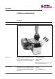
Danfoss CAN concept CAN components supplied by Danfoss can be identified from the abbreviation CIP (CAN Interfaced Product). We supply the following: • PVG CIP • Prof 1 CIP • CIP Configuration Tool Our objective is to supply CAN components which are not only capable of communicating with our own products, but also with other Prof 1 CIP The Prof 1 CIP joystick is available in many mechanical configurations.
CIP Configuration Tool The CIP Configuration Tool is a program developed for setting up systems consisting of PVG CIP and Prof 1 CIP. Code no. 155U.... 5670 Name CIP Configuration Tool Description Product contents • CIP Configuration Tool • CIP Downloading Utility • CANview • CAN dongle • Documentation, examples, help files Technical data Common to PVG CIP & Prof 1 CIP Power supply Supply voltage Max. supply voltage Max.
Prof 1 CIP data format The data format is independent of the mechanical configuration. It is manufactured so that a signal for an 8-bit processor can be extracted without signal manipulation. This gives 8bit signal resolution, and in order to get full resolution (10 bit) signal manipulation is necessary. This is standard on PVG CIP. The data format is “twos complement” and is shown in the figure below.
PVG CIP specification Electrical PVE outputs 8 PVE types that can be connected PVEO, PVEM, PVEH, PVES incl. versions with float position PVPX/PVPE outputs Resolution 1 9 bit (-100% to +100%) AMP part no. 1-967280-1, PCB-connector AMP part no. 1-967281-1, Timer house AMP part 0-929937-1, junior contact AMP part 0-962876-2, micro contact AMP part no. 0-965643-1, cover Seals and plugs Slave only Plug type (Only part no.
Prof 1 CIP specification Electrical Proportional signals max. Resolution Operating buttons on/off max. DIP switch settings DIP no. 1 DIP switch settings DIP no. 2 Plug type Only part no. 282404-1 and no. 282107-1 supplied Plug connections Pin number 1 2 3 4 5 Safety aspects 4 9 bit (-100% to +100%) 6 Open = CANopen min. master Closed = CANopen slave Open = Default baudrate and Node id Closed = Baudrate and Node id acc. to OD AMP part no. 282404-1, male plug AMP part no.
Fail-safe condition arises when faults of the following types occur: PVG CIP Description PVEs that go into fail-safe condition 1000 5000 5001 5002 5003 5004 5005 5006 5007 5008 5009 500A 500B 500C 500D 5016 6300 Generic fault System hardware Self-test fault, internal RAM Self-test fault, external RAM Self-test fault, EE-PROM Self-test fault, FLASH Self-test fault, feedback test # 1 Self-test fault, feedback test # 2 Self-test fault, feedback test # 3 Self-test fault, feedback test # 4 Self-test fault, f
Introduction to PVG CIP This component is located near the valve and acts as the interface between PVG and CAN bus. The interface can control up to eight PVEs and 1 PVPX/PVPE. 3) Setting system-related parameters a) Baudrate b) Node identification c) Softwiring System parameters can be set in the OD (see overview, page 25), either by using CIP Configuration Tool or with a normal CANopen Configuration Tool.
Identification of PVPX PVPX is used as a safety device for the PVG and dumps to tanks LS pressure in dangerous situations. With PVG CIP it is possible to select whether PVPX is to dump the LS pressure if a fault occurs in PVEH/PVES (pin 3). Units 0. PVPX N/A 1. PVPX present • Controlled by external source, e.g.
Baudrate The speed of communication must be set. The baudrate becomes effective after system reboot. Note: The baudrates 10 and 800 are not supported by CIP Configuration Tool v.1.00. Units Max. Min. Standard Precision OD index [kbit/s] 1000 10 250 * 201A HEX * 10, 20, 50, 100, 125, 250, 500, 800, 1000. Node identification Node identification specifies the address PVG CIP has for the other CAN components (applies after system reboot).
PVE input signal (%) / Spool position Joystick. Output signal (%) Flow (%) 1. The diagram shows the signal condition for only one port (e.g. port A). 2. Circles indicate parameters that can be set. The above diagram shows all functions in connection with one port, using four points A, B, C, and D.
Flow limitation (value Dy) This function limits the PVE output signal and thereby valve flow. The parameter is specified in percentage since the mechanical characteristics of the PVG CIP spool are not known. The function cannot be used in connection with on/off signals. Units Max. Min. Standard Precision OD index Software tuning of spool characteristics (points B, C) Used to change spool characteristics. This means that the spool need not be changed when only minor changes are necessary.
Ramps After signal tuning of points A-D as specified in the previous figure, the signal follows the ramp that is specified here. Two sets of ramps are available for each PVE output (see figure below). Both work on ramp principle 1, familiar in the EHR modules. Fast operation can be obtained by setting Tdown_A and Tdown_B on zero. The function cannot be used in connec-tion with on/off signals. Port A (Tup_A, Tdown_ A ) Port B (Tup_B, Tdown_ B ) Units Max. Min.
Float position control function The float position control function makes it possible to connect ports A and B to tank. This is performed mechanically by a specially designed spool. Two steps are necessary to activate the function: 1. The proportional function connected to the float position control function must be established. OD index The function can be deactivated in two ways: • If the joystick is moved towards port A by a signal of more than 10%.
Restoring factory settings Factory settings of all accessible parameters are stored permanently in PVG CIP. This function is used to restore all parameter settings to “Factory standard” by overwriting the existing parameter settings.
Introduction to Prof 1 CIP This component is based on the Prof 1 joystick and can therefore be set up for many mechanical configurations. The joystick also contains other functions often used on the hydraulics market. The associated parameters can be set in the OD (see page 29) either using the CIP Configuration Tool or standard CANopen configuration tools.
Node identification Node identification specifies which address Prof 1 CIP has. Units Max. Min. Standard Precision OD index 127 1 100 1 100B HEX Cyclic trigger The joystick sends information on the first PDO (tx). As standard, the joystick transfers cyclically using Tc = 10 ms. NMT is used if a fault arises in the joystick. The NMT object is a standard emergency object in CANopen. Units Max. Min.
Introduction to CIP Configuration Tool This program pack offers the user several different programs for meeting various requirements: CIP Configuration Tool Setting up a system consisting exclusively of PVG CIP and Prof 1 CIP via a graphical user interface. It takes the user through setting up a system in an easily understandable and instructive way. It cannot set up components from a third party.
Example of system setup via CIP Downloading Utility This is an example of setting up the parameters in connecting a Prof 1 CIP joystick with a PVG CIP.
1400, sub 1 Step 2: Setting up PVE types PVE (PVEM/H/S) types are used to select the PVG CIP control function. The types are defined in Index 2018, subindex 1-8 (see page 27). In this example the following changes have: Screen dump of type setup 22 HN.50.Y1.
Step 3: Connecting joystick signals to PVE outputs Connections between inputs and outputs in PVG CIP are made as follows: FORMAT OD 1400-1403 1st PDO VALUE OD 2100-2103 OUTPUT OD 2104 PROP1 PVE1 A PROP2 PVE1 B PROP3 PVE2 A PROP1 PROP4 PVE2 B PROP2 Push 3A PVE3 A PROP3 Push 3B PVE3 B PROP4 Push 4A PVE4 A REST Push 4B PVE4 B D1 1-8 Push 5 PVE5 A Push 6 PVE5 B Push 7 PVE6 A Push 8 PVE6 B PVE7 A 2nd PDO PROP1 PVE7 B PROP2 PVE8 A PROP3 PVE8 B PROP1 PROP4 PVPX PROP2
This means that in this example we must make the following connections in PVG CIP OD index 2104 HEX. *) *) Note: If a proportional signal is connected to, for example, PVE 3 B instead of A, the signal becomes inverted. 24 HN.50.Y1.
Parameter list 1 of 5 for PVG CIP (shortened version of OD) Index Parameter Name Index Subindex 1000 Subindex Device Type 1601 3 Prop3 Parameter Name 1001 Error Register 1601 4 Prop4 1003 error field 1601 5 Rest 1003 0 Number of errors 1601 6 Push3A 1003 1 Standard error code 1601 7 Push3B Number of PDOs supported 1601 8 Push4A 1004 1004 0 Number of PDOs supported 1601 9 Push4B 1004 1 Number of synchronous PDOs 1601 A Push5 1004 2 Number of asynchronous PD
Parameter list 2 of 5 for PVG CIP (shortened version of OD) Index Subindex Parameter Name Index Subindex 2001 6 DBC_6_AY_A 2007 4 FLOW LIMIT_4_DY_B 2001 7 DBC_7_AY_A 2007 5 FLOW LIMIT_5_DY_B 2001 8 DBC_8_AY_A 2007 6 FLOW LIMIT_6_DY_B Deadband_AX_B 2007 7 FLOW LIMIT_7_DY_B 8 2002 2002 0 Number of PVEs 2007 2002 1 DBC_1_AX_B 2008 2002 2 DBC_2_AX_B 2008 0 Number of PVEs 2002 3 DBC_3_AX_B 2008 1 SW TUNE_1_BX_A 2002 4 DBC_4_AX_B 2008 2 SW TUNE_2_BX_A 2002 5
Parameter list 3 of 5 for PVG CIP (shortened version of OD) Index Subindex Parameter Name Index Subindex Parameter Name 200D 2 SW TUNE_2_BY_B 2013 0 Number of PVEs 200D 3 SW TUNE_3_BY_B 2013 1 RAMP1_1_TDOWN_B 200D 4 SW TUNE_4_BY_B 2013 2 RAMP1_2_TDOWN_B 200D 5 SW TUNE_5_BY_B 2013 3 RAMP1_3_TDOWN_B 200D 6 SW TUNE_6_BY_B 2013 4 RAMP1_4_TDOWN_B 200D 7 SW TUNE_7_BY_B 2013 5 RAMP1_5_TDOWN_B 200D 8 SW TUNE_8_BY_B 2013 6 RAMP1_6_TDOWN_B SW TUNE CX B 2013 7 RAMP1_
Parameter list 4 of 5 for PVG CIP (shortened version of OD) Index Subindex Parameter Name Index Subindex Parameter Name 2018 8 TYPE_8 2101 0 Number of entries 2018 9 PVPX AVAILABLE 2101 1 Prop1 RAMP MODE 2101 2 Prop2 2019 2019 0 Number of PVEs 2101 3 Prop3 2019 1 RAMP MODE_1 2101 4 Prop4 2019 2 RAMP MODE_2 2101 5 Push3A 2019 3 RAMP MODE_3 2101 6 Push3B 2019 4 RAMP MODE_4 2101 7 Push4A 2019 5 RAMP MODE_5 2101 8 Push4B 2019 6 RAMP MODE_6 2101 9 P
Parameter list 5 of 5 for PVG CIP (shortened version of OD) Index Subindex 2104 10 PVE8B 2104 11 PVPX 2105 0 Number of entries 2105 1 PVE1 2105 2 PVE2 2105 3 PVE3 2105 4 PVE4 2105 5 PVE5 2105 6 PVE6 2105 7 PVE7 2105 8 PVE8 Index Subindex 2105 Parameterlist for Prof 1 CIP (shortened version of OD) Parameter Name Float PVE push mapping Parameter Name Index Subindex 1000 Device Type 1A00 6 Parameter Name 1001 Error Register 3000 Baudrate 1003 Pre-defined e
PVG CIP dimensions 30 HN.50.Y1.
HN.50.Y1.
Danfoss can accept no responsibility for possible errors in catalogues, brochures and other printed material. Danfoss reserves the right to alter its products without notice. This also applies to products already on order provided that such alterations can be made without subsequential changes being necessary in specifications already agreed. All trademarks in this material are property of the respective companies. Danfoss and the Danfoss logotype are trademarks of Danfoss A/S. All rights reserved.