
Technical data


10 HN.50.Y1.02
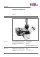
This component is located near the valve and
acts as the interface between PVG and CAN
bus. The interface can control up to eight
PVEs and 1 PVPX/PVPE.
System parameters can be set in the OD (see
overview, page 25), either by using CIP Confi-
guration Tool or with a normal CANopen Con-
figuration Tool.
Setting up PVG CIP can be divided into four
main parts:
1) Identification of components
a) Identification of PVE
b) Identification of PVPX/PVPE
2) Setting up connections
a) To other components on bus
(Prof 1 CIP)
b) Between data (joystick signals) and
PVE/PVPX
3) Setting system-related parameters
a) Baudrate
b) Node identification
c) Softwiring
4) Setting hydraulic-related parameters
a) Deadband compensation
b) Signal gain
c) Flow limitation
d) Software tuning of spool characteristics
e) Ramps (individual on each port, two
different settings for each port)
f) Float position control
g) Power saving
These components also contain facilities for
fault location, servicing and restoring factory
setting.
Component identification
To be able to communicate with PVG CIP it is
necessary to identify the system components:
• Identification of PVE type
• Identification of PVPX/PVPE type
Identification of PVE type Type identification is used to specify how PVG
CIP is to control the PVEs. The types used are
specified as follows:
0: Not accessible
1: PVEO
Units
2: PVEM
3: PVEH/S
4: PVEM (float position control)
5: PVEH (float position control)
Max. 5
Min. 0
Standard 3 (PVEH/S)
Precision 1
OD index 2018 HEX
PVE pins PVEH/S PVEM PVEO
1 + + Port A
2 Signal Signal Port B
3 Alarm N/A N/A
Frame Frame Frame
PVG CIP output/input will be on the following PVE pins, depending on type
Introduction to PVG CIP