
Technical data


HN.50.Y1.02 13
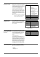
The above diagram shows all functions in con-
nection with one port, using four points A, B,
C, and D. Points A and D define the limits of
the graph and thus the range of the functions
that transform a joystick signal to a PVE out-
put in the PVG CIP which then controls the
position of the spool in the valve accordingly.
A : Defines deadband compensation and
initial flow.
B, C : Defines software tuning of the spool
characteristics. Coordinates for B and
C are specified to suit the graph and
must be scaled every time A and D are
changed. This means that seen from
points B and C, A always corresponds
to (0,0) and D always to (100,100).
D : Defines joystick gain and flow
limitation.
1. The diagram shows the signal condition for only one port
(e.g. port A).
2. Circles indicate parameters that can be set.
PVE input signal (%) /
Spool position
Flow (%)
Joystick.
Output signal (%)
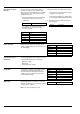
Deadband compensation
(point A)
This function compensates for the deadband
in the PVG spool. The parameters specify a
set of coordinates and linear interpolation is
performed from (joystick signal, 0) to the
function when the deadband compensation is
worked out. The function cannot be used in
connection with on/off signals.
Joystick signal, PVG CIP output signal
The joystick signal can be scaled with this
function. The function cannot be used in con-
nection with on/off signals.
Note: 100% corresponds to normal ampli-
fication. Lower figures give larger
amplification.
Units [%]
Max. 100
Min. 25
Standard 100
Precision 1
OD index
2004 HEX port A
2005 HEX port B
Units [x, y]: [%,%]
Max. (100, 100)
Min. (0,0)
Standard (0,0)
Precision (1,1)
2000 HEX port A x-coordinate
OD index
2001 HEX port A y-coordinate
2002 HEX port B x-coordinate
2003 HEX port B y-coordinate
Signal gain
(value D
x
)