
Data Sheet


Page 10
Web: www.maxbotix.com
PD11721l
MaxBotix
®
Inc.
Copyright 2005 - 2014 MaxBotix Incorporated
Patent 7,679,996
HRLV-MaxSonar
®
-
EZ
™
Series
MaxBotix Inc., products are engineered and assembled in the USA
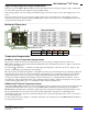
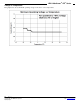
Selecting a HRLV-MaxSonar-EZ
Different applications require different sensors. The HRLV-MaxSonar-EZ product line offers varied sensitivity to allow
you to select the best sensor to meet your needs.
The diagram above shows how each product balances sensitivity and noise tolerance. This does not affect the maximum
range, pin outputs, or other operations of the sensor. To view how each sensor will function to different sized targets
reference the HRLV-MaxSonar-EZ-Beam Patterns.
_______________________________________________________________________________________________________________________________________
HRLV-MaxSonar
®
-EZ
™
Beam Patterns
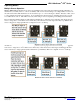
Background Information Regarding our Beam Patterns
Each HRLV-MaxSonar-EZ sensor has a calibrated beam pattern. Each sensor is matched to provide
the approximate detection pattern shown in this datasheet. This allows end users to select the part
number that matches their given sensing application. Each part number has a consistent field of
detection so additional units of the same part number will have similar beam patterns. The beam
plots are provided to help identify an estimated detection zone for an application based on the
acoustic properties of a target versus the plotted beam patterns.
Each beam pattern is a 2D representation of the detection area of the sensor. The beam pattern is
actually shaped like a 3D cone (having the same detection pattern both vertically and horizontally).
Detection patterns for dowels are used to show the beam pattern of each sensor. Dowels are long
cylindered targets of a given diameter. The dowels provide consistent target detection characteristics
for a given size target which allows easy comparison of one MaxSonar sensor to another MaxSonar
sensor.
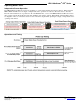
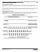
For each part number, the four patterns (A, B, C, and D) represent the detection zone for a given target size. Each beam
pattern shown is determined by the sensor’s part number and target size.
The actual beam angle changes over the full range. Use the beam pattern for a specific target at any given distance to
calculate the beam angle for that target at the specific distance. Generally, smaller targets are detected over a narrower
beam angle and a shorter distance. Larger targets are detected over a wider beam angle and a longer range.
People Sensing:
For users that
desire to detect
people, the
detection area to
the 1-inch
diameter dowel, in
general, represents
the area that the
sensor will
reliably detect
people.