
Data Sheet


Page 2
Web: www.maxbotix.com
PD11721l
MaxBotix
®
Inc.
Copyright 2005 - 2014 MaxBotix Incorporated
Patent 7,679,996
HRLV-MaxSonar
®
-
EZ
™
Series
MaxBotix Inc., products are engineered and assembled in the USA
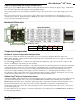
Pin Out Description
Pin 1- Temperature Sensor Connection: Leave this pin unconnected if an external
temperature sensor is not used. For best accuracy, this pin is optionally connected to the
HR-MaxTemp temperature sensor. Look up the HR-MaxTemp temperature sensor for
additional information.
Pin 2- Pulse Width Output: This pin outputs a pulse width representation of the distance
with a scale factor of 1uS per mm. Output range is 300uS for 300-mm to 5000uS for
5000-mm. Pulse width output is +/- 1% of the serial data sent.
Pin 3- Analog Voltage Output: On power-up, the voltage on this pin is set to 0V, after
which, the voltage on this pin has the voltage corresponding to the latest measured distance.
This pin outputs an analog voltage scaled representation of the distance with a scale factor of (Vcc/1024) per 5-mm. (This
output voltage is referenced to GND, Pin 7.) The analog voltage output is typically within ±10-mm of the serial output.
Using a 10bit analog to digital convertor, one can read the analog voltage bits (i.e. 0 to 1023) directly and just multiply the
number of bits in the value by 5 to yield the range in mm. For example, 60 bits corresponds to 300-mm (where 60 * 5 =
300), and 1000 bits corresponds to 5000-mm (where 1000 * 5 = 5000-mm).
For users of this output that desire to work in voltage, a 5V power supply yields~4.88mV per 5 mm. Output voltage range
when powered with 5V is 293mV for 300-mm, and 4.885V for 5000-mm.
Pin 4- Ranging Start/Stop: This pin is internally pulled high. If this pin is left unconnected or held high, the sensor will
continually measure and output the range data. If held low, the HRLV-MaxSonar-EZ will stop ranging. Bring high for
20uS or longer to command a range reading.
Real-time Range Data: When pin 4 is low and then brought high, the sensor will operate in real time and the first reading
output will be the range measured from this first commanded range reading. When the sensor tracks that the RX pin is low
after each range reading, and then the RX pin is brought high, unfiltered real time range information can be obtained as
quickly as every 100mS.
Filtered Range Data: When pin 4 is left high, the sensor will continue to range every 100mS, but the output will pass
through a 2Hz filter, where the sensor will output the range based on recent range information.
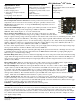
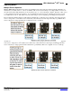
Pin 5-Serial Output: By default, the serial output is RS232 format (0 to Vcc) with a 1-mm resolution. If TTL
output is desired, solder the TTL jumper pads on the back side of the PCB as shown in the photo to the right.
For volume orders, the TTL option is available as no-cost factory installed jumper. The output is an ASCII
capital “R”, followed by four ASCII character digits representing the range in millimeters, followed by a
carriage return (ASCII 13). The maximum distance reported is 5000. The serial output is the most accurate of the range
outputs. Serial data sent is 9600 baud, with 8 data bits, no parity, and one stop bit.
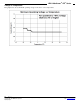
V+ Pin 6 - Positive Power, Vcc: The sensor operates on voltages from 2.5V - 5.5V DC. For best operation, the sensor
requires that the DC power be free from electrical noise. (For installations with known dirty electrical power, a 100uF
capacitor placed at the sensor pins between V+ and GND will typically correct the electrical noise.) Please reference page
5 for minimum operating voltage verses temperature information.
GND Pin 7 – Sensor ground pin: DC return, and circuit common ground.
About Ultrasonic Sensors
Our ultrasonic sensors are in air, non-contact object detection and ranging sensors that detect objects within an area. These
sensors are not affected by the color or other visual characteristics of the detected object. Ultrasonic sensors use high
frequency sound to detect and localize objects in a variety of environments. Ultrasonic sensors measure the time of flight
for sound that has been transmitted to and reflected back from nearby objects. Based upon the time of flight, the sensor
then outputs a range reading.
Applications & Uses
• Proximity zone detection
• People detection
• Robots ranging sensor
• Autonomous navigation Distance
measuring
• Long range object detection
• Automated factory systems
• This product is not recommended as
a device for personal safety
• Designed for protected indoor envi-
ronments
• Motion detectors
• Limited tank level measurements
• Box dimensions
• Environments with acoustic and elec-
trical noise
• Height monitors
• Auto sizing