
Datasheet


Copyright 2005 - 2021 MaxBotix Incorporated Patent 7,679,996
XL-MaxSonar
®
- EZ/AE™ Series
Page 6
Web: www.maxbotix.com
PD11840l
MaxBotix Inc., products are engineered and assembled in the USA.
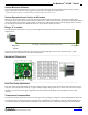
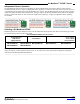
Sensor Timing Diagrams
Power Up Timing
Sensor Free-Run Timing
Real-Time Operation
Timing Description
175mS after power-up, the XL-MaxSonar is ready to begin ranging. If Pin-4 is left open or held high (20uS or greater),
the sensor will take a range reading. The XL-MaxSonar checks the Pin-4 at the end of every cycle. Range data can be
acquired once every 99mS. Each 99mS period starts by Pin-4 being high or open, after which the XL-MaxSonar calibrates
and calculates for 20.5mS, and after which, twenty 42KHz waves are sent.
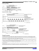
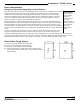
At this point, for the MB1260, the pulse width (PW) Pin-2 is set high and until an object is detected after which the pin is
set low. If no target is detected the PW pin will be held high for up to 44.4mS
1
(i.e. 58uS * 765cm) or 62.0mS
2
(i.e. 58uS
* 1068cm). (For the most accurate range data, use the PW output.)
For the MB1300 sensor series, the analog envelope output, Pin-2, will show the real-time signal return information of the
analog waveform.
For both parts, the remainder of the 99mS time (less 4.7mS) is spent adjusting the analog voltage to the correct level, (and
allowing the high acoustic power to dissipate). During the last 4.7mS, the serial data is sent.