
Product guide

134 Technical Reference 135MAXDATA PLATINUM 90002R Server System
POST Error Codes and Messages
In order to indicate progress through BIOS POST, and in special cases where errors are encountered
during BIOS POST, there are three common mechanisms that shall be employed by the server system
BIOS. The rst method is to display port 80/81 codes to an I
2
C adapter connected to the main board.
The second common method is the use of beep codes, encoded beep sequences emitted by the PC
speaker when an error is encountered. Beep codes are employed only before the display screen is
enabled, and generally indicate fatal errors. Beep codes are coupled with special port 80 error codes.
The nal method is to display an error message to the display screen.
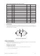
North and South Port 80/81 Cards
The port 80 card is a custom device that is attached to I
2
C ports in two different places on the
server. One port 80 device serves the north ash ROM and the other serves the south ash ROM.
Both headers are located on the main board; the north bridge is ag J6G1 and the south bridge is at
J5G1.
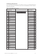
POST Codes
POST Codes Module Map
The Server System MAXDATA PLATINUM 9000-2R employs a novel POST code scheme. POST
codes assigned make use of the fact that the server system utilizes port 80h and 81h. This gives the
system 16 bits to encode. The following rules apply to the POST code encoding, except bit 14 and 15
encoding for SALB, SALC and SALF:
• Bit 15: 1 – Itanium
®
-based code being executed, 0 – IA-32 code being executed
• Bit 14: 1 – system stopped due to known failure, 0 – progress indication
For SALB, SALC and SALF modules:
• Bit 15: 1 – Itanium
®
-based code being executed
0 – system stopped due to known failure
• Bit 14: not used, always 0 All other module bits remain unmodied.
• Bit 13: 1 – fault or trap (no change in module numbers)
0 – normal execution
In case of fault or trap, only bit 13 is set and other bits are left on modied. This allows us to
detect which module produces the fault.
• Bit 12: Reserved
• Bit 11-4: Module number
• Bit 3-0: Sub module number
The module number and sub-module number are separated by a 4-bit boundary to allow us to decode
quickly. The module number identies the major module such as memory, PCI, ACPI, etc. The sub
module number identies the sub function such as SPD read in progress, ECC error, and DIMM
mismatch for memory module.
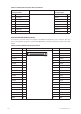
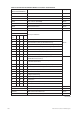
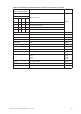
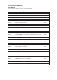
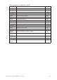
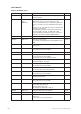
Module names and numbers are listed in the following tables.
• Bit 11:8 – 0xF stack-less code being executed
0xE-0x0 – memory is available