
Product guide


36 Board Set Description
37MAXDATA PLATINUM 90002R Server System
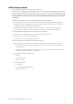
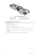
SCSI Backplane Board
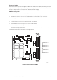
The SCSI backplane board connection layout is shown in
Figure 20. The SCSI backplane board communicates with the main board via a 68-pin SCSI cable and
to the Front Panel board via a 20-pin ribbon cable. It contains two industry standard 80-pin Single
Connector Attachment (SCA)-2 connectors for hot-swap hard drives. Ultra320 or lower SCSI technology
SCA type hard drives can be installed in this carrier. The backplane board accepts hard drives up to
15,000-RPM.
The features supported by the SCSI backplane board include the following:
• Monitoring the SCSI bus for enclosure services messages and acting on them appropriately.
Examples of such messages include: activate a drive fault indicator, power down a drive that
has failed, and report SCSI backplane temperature.
• SAF-TE intelligent agent, which acts as proxy for “dumb” I
2
C devices during intra-chassis
communications. “Dumb” I
2
C devices are those that have no bus mastering capability.
The SCSI backplane provides three main functions for the system:
• It passes the SCSI signals between the main board and the SCSI drives
• It provides hooks for enclosure management
• It provides an I
2
C server management interface
The SCSI backplane functional blocks include the following:
• Ultra320 LVD SCSI bus passes SCSI signals between the SCSI drives and the main board
– A standard 68-pin SCSI connector provides the SCSI connection from the main board to the
SCSI backplane
– Two 80-pin (SCA-2 blind-mate) connectors are located on the SCSI backplane board to mate
with hot-swap LVD SCSI drives in the drive bay
• Fault Tolerant Enclosure Management
– SAF-TE
– SCSI power control
– LED control logic
• Server management
– I
2
C interface
– I
2
C Serial CMOS EEPROM (FRU)
– Temperature sensor