
Product guide


38 Board Set Description
39MAXDATA PLATINUM 90002R Server System
Front Panel Board
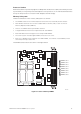
The front panel board connection layout is displayed in Figure 21. The front panel board provides three
main functions for the system:
• It passes the IDE signals between the main board and the DVD drive
• It provides the front panel interface for the system
• It provides I
2
C server management interface
Front Panel Board Functional Blocks
• IDE bus passes IDE signals between the IDE DVD and the main board
– The 120 pin flex cable connector from main board provides IDE connectivity and auxiliary
signals
– Single IDE channel pass-thru connection to IDE connector for support of an IDE peripheral
• Front panel functions
– Two USB 1.1 connections
– Power, Reset, SDINT and ID buttons
– LEDs for power, both NIC channels, ID, system and drive failure
– VGA connector providing video from main board controller
• Server management
– I
2
C isolation to SCSI board
– Temperature sensor
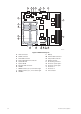
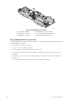
Figure 21. Front Panel Board Layout
A. Ribbon connector to SCSI backplane board
B. Power connector from SCSO backplane board
C. Flex cable to main board
D. IDE connector
E. Front panel buttons, LEDs, USB, video connector