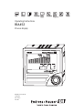
Operating Instructions RIA452 Process display BA254R/24/ae/09.07 71064276 SW version 2.01.
Brief overview For rapid and easy commissioning: Safety instructions → ä4 Æ Installation → ä8 Æ Wiring → ä 10 Æ Display and operating elements → ä 21 Æ Commissioning → ä 25 Device configuration - explanation and use of all the configurable device functions with the associated value ranges and settings. Block circuit diagram G09-RIA452xx-05-00-xx-en-000 Fig.
Table of contents 1 Safety instructions . . . . . . . . . . 4 10 Technical data. . . . . . . . . . . . . 63 1.1 1.2 1.3 1.4 1.5 Designated use . . . . . . . . . . . . . . . . . . . . . . Installation, commissioning and operation . Operational safety . . . . . . . . . . . . . . . . . . . Return . . . . . . . . . . . . . . . . . . . . . . . . . . . . Notes on safety conventions and icons . . . . 2 Identification . . . . . . . . . . . . . . 6 10.1 10.2 10.3 10.4 10.5 10.6 10.7 2.1 2.2 2.
Safety instructions 1 Safety instructions Safe operation of the process display unit is only guaranteed if these Operating Instructions have been read and the safety instructions have been observed. 1.1 Designated use The process display unit analyzes analog process variables and depicts them on its multicolored display. Processes can be monitored and controlled using analog and digital outputs and limit relays. The device provides the user with a wide range of software functions for this purpose.
Safety instructions 1.5 Notes on safety conventions and icons The safety instructions in these Operating Instructions are labeled with the following safety icons and symbols: " Caution! This symbol indicates an action or procedure which, if not performed correctly, can result in incorrect operation or destruction of the device. # Warning! This symbol indicates an action or procedure which, if not performed correctly, can result in injury, a safety hazard or the destruction of the device.
Identification 2 Identification 2.1 Device designation 2.1.1 Nameplate Compare the nameplate on the device with the following diagram: G09-RIA452xx-18-00-xx-xx-000 Fig. 2: Nameplate of the process display unit (example) 1 2 3 4 5 Order code and serial number of the device Power supply Software version number Ambient temperature Performance 2.
Identification 2.3 Certificates and approvals CE mark, declaration of conformity The process display unit is designed to meet state-of-the-art safety requirements, has been tested and left the factory in a condition in which it is safe to operate. The device meets the relevant standards and directives as per IEC 61 010-1 "Safety requirements for electrical equipment for measurement, control and laboratory use".
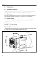
Installation 3 Installation 3.1 Installation conditions The permitted ambient conditions (see Section 10 "Technical data") must be observed when installing and operating. The device must be protected against the effects of heat. 3.1.1 Dimensions Please note the installation depth of 150 mm (5.91 inches) for the measuring instrument plus cable. Additional dimensions are provided in Fig. 3 and Section 10 "Technical data". 3.1.2 Mounting location Installation in panel with 92x92mm (3.62x3.
Installation 1. Push the device with the sealing ring (item a) through the panel cutout from the front. 2. Keep the device horizontal and suspend the two fixing clips (item b) in the recesses provided. 3. Tighten the screws of the fixing clips evenly with a screwdriver. 4. Remove the protective strip from the display. The dimensions of the process display unit are provided in the "Technical data" Section.
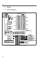
Wiring 4 Wiring 4.1 Quick wiring guide G09-RIA452ZZ-04-01-xx-en-000 Fig.
Wiring Terminal assignment Terminal Terminal assignment L/L+ L for AC L+ for DC N/L- N for AC L- for DC NC Not connected J1 Jumper for locking device operation via hardware. If the jumper is set to J1, the configuration cannot be modified.
Wiring Terminal Terminal assignment 54 Normally closed (NC) 55 Common (COM) 56 Normally open (NO) 141 Normally closed (NC) 142 Common (COM) 143 Normally open (NO) 151 Normally closed (NC) 152 Common (COM) 153 Normally open (NO) 144 Normally closed (NC) 145 Common (COM) 146 Normally open (NO) 154 Normally closed (NC) 155 Common (COM) 156 Normally open (NO) 96 Ground for digital status inputs 97 + digital status input 1 197 + digital status input 2 297 + digital status
Wiring Terminal Terminal assignment 33 + digital output 34 Ground, digital output 91 24 V sensor power supply 2 92 Ground, sensor power supply 2 Type Digital output (optional) Transmitter power supply Universal input option The device can be optionally equipped with a universal input instead of a current input. G09-RIA452xx-04-10-xx-en-002 Fig.
Wiring Terminal assignment Terminal Terminal assignment 11 + 0/4 to 20 mA signal 12 Signal ground (current, voltage, temperature) 13 + 1 V, + thermocouples, - resistance thermometer signal (3/4 wire) 15 + resistance thermometer signal (4-wire) 17 + 30 V 19 + resistance thermometer power supply (3-wire/4-wire) 4.2 " Connecting the device Caution! Do not install or wire the device when it is connected to the power supply.
Wiring 4.2.2 Connecting external sensors ! Note! Active and passive sensors with analog, TC, resistance and RTD sensors can be attached to the device. Depending on the type of signal of the sensor in question, the terminals can be freely selected. Current input 0/4 to 20 mA G09-RIA452xx-04-10-xx-en-001 Fig. 7: Connection of the two-wire sensor to the current input 0/4 to 20 mA Universal input G09-RIA452xx-04-10-xx-en-003 Fig.
Wiring 4.
Operation 5 Operation 5.1 Quick operation guide M1 M2 M3 Analog input INPUT Display DISPLAY. Analog output* ANALOG OUT Signal type Connection type* Curve Signal damping Signal type Connection Curve Damp Dimension Decimal point 0% value 100% value Dimension Dec. point 0% value 100% value Offset Comparative temperature * Fixed comparative temp.* Open circuit detection Offset Comp. temp. Const. temp. Open circ.
Operation M5 M10M17 M18 Digital input 1-4 DIGITAL INP. Limit 1-4 (8)* LIMIT Integration* Integration Value in the event of a fault Simulation mA Simulation Volt Fail value Simu mA Simu V Function digital input 1-4 Active level1-4 Pump monitoring sampling time Function Level Sampl. time Assignment Function 1-4 (8) Decimal point Switch point A Switch point B Ref. num Function Dec.
Operation M19 Pulse output* PULSE OUT Reset totalizer Flow calculation Dimension of input signal Dimension of linearized value Decimal point for formula Reset total Calc flow Dim. Input Dim. flow Dec. flow Decimal point for display Alpha value Beta value Gamma value C value Dec.
Operation M20 M21 M23Mxx M55 Min/Max memory MIN/MAX Signal source for Min/Max Decimal point Display minimum value Ref. min/max Dec. point Min. value Display maximum value Reset minimum vaule Reset maximum value Max. value Reset min Reset max Number of support points Dimension of linearized value Decimal point Y-axis Delete all support points Display all support points Counts Dimension Dec. Y value Del points Show points Lin.
Operation 5.2 Display and operating elements G09-RIA452xx-19-00-06-xx-000 Fig. 9: Display and operating elements 1) 2) 3) 4) 5) 6) 7) 8) 9) Green operating indicator, lights up when supply voltage is applied Red fault indicator, flashes in event of sensor or device error Limit value display: if power is supplied to a relay, the symbol is displayed.
Operation Range Display Relay Analog output Integration Input current below upper error limit and above upper limitations of validity Display " " Normal limit value behavior Normal behavior with max. 10% overrange. No output < 0 mA possible.
Operation B) Selection from list Æ Arrow pointing down: Option is at the top of the picklist. The other entries become visible when the jog/shuttle is turned in the clockwise direction. Å Both arrows visible: Æ User is in the middle of the picklist. Å Arrow pointing up: The end of the picklist is reached. The user moves back towards the start when the jog/shuttle is turned in the counterclockwise direction. G09-RIA452ZZ-19-00-00-xx-003 Fig. 11: Selecting from list via jog/shuttle dial 5.3.
Operation Possible characters The following characters can be entered: Space +ABCDEFGHIJKLMNOPQRSTUVWXYZabcdefghijklmnopqrstuvwxyz0123456789/\%°23+-.; :*() followed by return symbol (arrow to left) 5.3.3 Disabling the programming mode User code The configuration can be protected against unintentional access by means of a four-digit code. This code is defined in the submenu "Parameter/User Code". All the parameters remain visible on the display but the "key" symbol is shown on the display.
Commissioning 6 Commissioning 6.1 Function check Make sure that all post-connection checks have been carried out before you commission your device: • Checklist Section 4.3 'Post-connection check' ! Note! Remove the protective strip from the display as this restricts display legibility otherwise. 6.2 Switching on the measuring device Once the operating voltage is applied, the green LED indicates that the instrument is operational.
Commissioning Function (menu item) Parameter setting Description Signal type 4 - 20 mA 0 - 20 mA 0 - 5 mA (*) 0 - 100 mV (*) 0 - 200 mV (*) 0 - 1 V (*) 0 - 10 V (*) ± 150 mV (*) ± 1 V (*) ± 10 V (*) ± 30 V (*) Type B (IEC584) (*) Type J (IEC584) (*) Type K (IEC584) (*) Type L (DIN43710) (*) Type L (GOST) (*) Type N (IEC584) (*) Type R (IEC584) (*) Type S (IEC584) (*) Type T (IEC584) (*) Type U (DIN43710) (*) Type D (ASTME998) (*) Type C (ASTME998) (*) PT50 (GOST) (*) PT100 (IEC751) (*) PT100 (JIS1604)
Commissioning Function (menu item) Parameter setting Description Curve Linear Quad. °C °F Kelvin Linear or quadratic (quad.) characteristic of the sensor used. Can be selected for analog signals. °C, °F, Kelvin physical measured variable, can be selected for temperature sensors. Damp 0..99.9 0 Signal damping of measuring input with 1st order low pass. Time constant can be selected from 0 to 99.9 sec.
Commissioning Adjusting the analog input The input can be adjusted to the sensor with the aid of the following parameters. For current, voltage and resistance sensors, a scaled value is calculated from the sensor signal: For temperature outputs, the scaled value is calculated from linearization tables. The temperature value can be converted to degrees Celsius, degrees Fahrenheit or Kelvin. In addition, the temperature value can be corrected by means of an offset.
Commissioning Function (menu item) Parameter setting Description Display sw. 0 to 99 sec 0 Selectable period for displaying the individual values if combinations of display values have been selected under Ref. num. This setting can only be selected if the pulse output or integration option is available and has been configured. Ref. bargraf Input Lintab Selects the signal source for the bar graph Dec. point XXXXX XXXX.X XXX.XX XX.XXX X.
Commissioning 6.3.3 Analog output - ANALOG OUT/M3 All configurable parameters for the analog output can be found under the analog output menu item which is marked as ANALOG OUT in the device. ! Note! This item is only available if the "Analog output" option is available in your device. Function (menu item) Parameter setting Description Ref. num. Input Lintab Selects which value is output at the analog output.
Commissioning Function (menu item) Parameter setting Description Fail mode Hold const Min Max Output value if a sensor or device error occurs. • Hold = last valid value • Const = freely selectable value • Min = output value 3.5 mA for 4 to 20 mA, otherwise 0 V or 0 mA • Max = output value 22.0 mA for 0/4 to 20 mA, otherwise 1.1 V or 11 V Fail value 0..999.99 0.00 The freely selectable value for "Fail mode = Const" can be set here.
Commissioning 6.3.4 Digital input - DIGITAL INP./M5 The settings for the digital status inputs, e.g. for monitoring pumps, starting/stopping the counter or resetting the min/max-value memory are grouped in this section. ! Note! – The digital inputs 1 to 4 are permanently assigned to relays 1 to 4 in the PUMP function. Relay 1 is monitored by digital input 1, relay 2 by digital input 2 etc. – When the "Batch" function is used, digital input 1 is permanently assigned to a preset value count function.
Commissioning Pump monitoring function If pump monitoring should be implemented, digital inputs 1 to 4 are permanently assigned to relays 1 to 4. This function is enabled for the corresponding digital input with the Function parameter. Pump must be selected here. In general, two different types of monitoring can be implemented. With fault monitoring, the signal at the digital input is changed if there is a fault at the pump.
Commissioning In event 5, the alarm relay and the error message on the display are acknowledged by pressing the jog shuttle. In event 6 and 7, the unproblematic operation of the system is indicated. b) Operation monitoring In the operation monitoring mode, a change in the status signal is expected at the related digital input once a pump has been triggered. A waiting time (Sampl. Time, T) is defined for this. The alternating system is activated.
Commissioning ! Note! A faulty pump is always brought back into service depending on the signal at the related digital input. Acknowledging the error message on the display does not have any effect on the pump going back into operation. If a pump is faulty for longer than 10 minutes, an attempt is made to bring the pump back into operation upon the next limit violation. The following parameters must be configured: Menu Function (menu item) Setting value DIGITAL INP./M5 Function Level Sampl.
Commissioning Function (menu item) Parameter setting Description Function Off Min Max Grad In band Out band Alarm Alarm inverse Selects limit value and fault monitoring. In the event of device errors or incorrect input values (see error limits Range 1 to 4 in Section 6.3.11), the relays are switched in accordance with the failsafe mode configured in Rel. Mode (see Section 6.3.11).
Commissioning Function (menu item) Parameter setting Description Sw. delay 0..99 0 The starting time for 24-hour counting can be selected with Sw. delay. Every time the instrument is reset, the process of measuring 24 hours and the delay time is restarted. Example see Page 43 Sw. period 0..999 0 Limit value is activated cyclically every 24 hours for 0 to 999 seconds. The activation is delayed by [Sw.delay] hours by changing the hour value (example see Page 43).
Commissioning Min operating mode G09-RIA452ZZ-15-00-xx-en-001 Fig.
Commissioning Max operating mode G09-RIA452ZZ-15-00-xx-en-002 Fig.
Commissioning Grad operating mode G09-RIA452ZZ-15-00-xx-en-006 Fig. 17: Grad operating mode The "Grad" operating mode is used for monitoring the changes in the input signal over time. The time basis Tm of the monitoring system is configured in the "PARAMETER/M55 -> Grad. time" menu. The difference between the lower range value M0-m and the upper range value M0 of the interval is calculated.
Commissioning • EEPROM HW error (E101) The relay remains picked up even after acknowledging. • Implausible calibration data (E103) The relay remains picked up even after acknowledging. • Bus error reading the min/max data after power-up (E104) The relay remains picked up even after acknowledging. • Bus error reading the relay data after power-up (E105) The relay remains picked up even after acknowledging. • Universal card HW error (E106) The relay remains picked up even after acknowledging.
Commissioning Alternate Measured value Mode Max Setpoint A 3 Setpoint A 3 - Hysterese 3 Setpoint A 2 Setpoint A 2 - Hysterese 2 Setpoint A 1 Setpoint A 1 - Hysterese 1 t Switching status With alternating pump control Relay 3 Relay 2 Relay 1 t Switching status Relay 3 Without alternating pump control Relay 2 Relay 1 t Relay currentless G09-RIA452ZZ-15-00-xx-en-007 Fig.
Commissioning ! Note! Relays not included in alternating pump control are available. This function cannot be applied to individual relays. Relays not included are not assessed based on the switch-on and switch-off duration.
Commissioning 6.3.6 INTEGRATION/M18 This function can only be selected if the pulse output option is available in the device. ! Note! If the preset counter function (Batch) is used, digital input 1 and relay 1 and 2 are permanently assigned to this function. Configuration for these inputs/outputs is then not possible. Function (menu item) Parameter setting Description Ref. integr. Input Lintab Selects which value should be integrated.
Commissioning Function (menu item) Parameter setting Description Set count A 999999 0.0 End value/start value for preset counter; refers permanently to relay 1. Set count B 999999 0.0 Value for preliminary alarm; refers permanently to relay 2. Totalizer 9999999 In this position, the totalizer can be displayed and edited (e.g. assigned a default value). ! Note! The counter starts again at 0 if the maximum value of 9999999 is exceeded. Reset total Calc.
Commissioning Function (menu item) Parameter setting Description m3/s, l/s, hl/s, igal/s, usgal/s, barrels/s, inch3/s, ft3/s, Usmgal/s, Ml/s, m3/smin, l/min, hl/min, igal/min, usgal/min, barrels/min, inch3/min, ft3/min, Usmgal/min, Ml/min, m3/h, l/h, hl/h, igal/h, usgal/h, barrels/h, inch3/h, ft3/h, Usmgal/h, Ml/h Dimension of linearized value • l = liter • hl = hectoliter • m3 = cubic meter • Ml = megaliter • USgal = US gallon • USKgal = US kilogallon • USMgal = US megagallon Dec. point XXXXX XXXX.
Commissioning Function (menu item) Parameter setting Description Khafagi-Venturi channels ISO-Venturi channels Venturi channels as per British Standard Parshall channels Parshall-Bowlus channels Rectangular weir (w) Rectangular weir with constriction (w) Rectangular weir as per NFX (w) Rectangular weir as per NFX with constriction (w) Trapezoidal weir (w) Triangular ("V") weir (w) Triangular weir as per British Standard Triangular weir as per NFX Configure (w) width additionally Flumes weir Kha Ventur
Commissioning Function (menu item) Parameter setting 4" 7" 12" 18" 30" Venturi channels as per British Standard 4" = Venturi channel as per British Standard 4 inch 7" = Venturi channel as per British Standard 7 inch 12" = Venturi channel as per British Standard 12 inch 18" = Venturi channel as per British Standard 18 inch 30" = Venturi channel as per British Standard 30 inch 1" 2" 3" 6" 9" 1 ft 1.
Commissioning Function (menu item) Parameter setting 2H 3H 4H 5H 6H 8H TO T5 2T Rectangular weir with constriction 2H = rectangular weir with constriction 2H 3H = rectangular weir with constriction 3H 4H = rectangular weir with constriction 4H 5H = rectangular weir with constriction 5H 6H = rectangular weir with constriction 6H 8H = rectangular weir with constriction 8H TO = rectangular weir with constriction TO T5 = rectangular weir with constriction T5 2T = rectangular weir with constriction 2T 5H T5
Commissioning Function (menu item) Parameter setting NFX V-weir 30 45 60 90 Description NFX triangular weir 30 = NFX triangular weir 30 45 = NFX triangular weir 45 60 = NFX triangular weir 60 90 = NFX triangular weir 90 Integration function With this function, the computed value from the linearization table or the current flow value for channel calculation, or that of the analog input can be numerically integrated to create a totalizer for example.
Commissioning Thus, the number of free relays available is reduced accordingly. The operating menus for these inputs/outputs are then hidden. Set count B (LV B) defines the preliminary switchoff, Set count A (LV A) defines the main switchoff.
Commissioning Function (menu item) Parameter setting Description Dec. value XXXXX XXXX.X XXX.XX XX.XXX X.XXXX Decimal point position of the pulse value. Unit value 0..99999 1.0 Pulse value with which the pulses should be output at the output. Pulse width 0.04 to 2000ms 1000.00 Sets the pulse width at the pulse output. Off 1 Hz 10 Hz 100 Hz 1000 Hz 10000 Hz Outputs the selected pulses at the pulse output regardless of the input value. Is automatically set to OFF when exited.
Commissioning Function (menu item) Parameter setting Description Dec. point XXXXX XXXX.X XXX.XX XX.XXX X.XXXX Number of digits after the decimal point for the min/max value memory. Min. value 0..99999 Displays the current minimum value in the memory. Max. value 0..99999 Displays the current maximum value in the memory. Reset min No Yes Resets the minimum value memory. Reset max No Yes Resets the maximum value memory. 6.3.9 Linearization table - LIN.
Commissioning Function (menu item) Show points Parameter setting No Yes Description Show all programmed support cells. Tank linearization Example: G09-RIA452ZZ-15-00-xx-xx-011 Fig. 22: Example for tank linearization You want to determine the amount of cereal filled into a silo, display this information on site and transfer it to a process control system.
Commissioning – – – – Level 10 m Numeric display should show 1500 (m3) Bar graph should show 100% 20 mA should be present at the analog output Point 1 2 3 4 5 6 7 8 9 10 Sensor signal (mA) X value 4,0 X value 4.32 X value 4.64 X value 4.96 X value 5.28 X value 5.6 X value 5.92 X value 6.24 X value 6.56 X value 20.
Commissioning 6.3.10 Support points of linearization table - LINPOINTS 1..X/M23..MXX Displays the set value pairs of the linearization table. This menu item is only visible if a linearization table was configured under Section 6.3.9 and "Yes" was selected in the "Show points" parameter in the "LIN. TABLE/M21" menu. Function (menu item) Parameter setting Description Point Used Discard Use or discard support point. X value -99999..99999 X-value of the linearization table.
Commissioning Function (menu item) Parameter setting Description Version V X.XX.XX Version of the device software currently installed. Func. alt. Time Count Setting for controlling pump rotation in alternating pump control. • Time = switching time of the relay • Count = switching frequency of the relay Lock time 99.9 Locking time of the relay, 0 to 99.9 s Rel. Mode Off On Switching behavior of the relays.
Maintenance 7 Maintenance No special maintenance work is required on the device. 8 58 Accessories Name Order No. ReadWin® 2000 PC configuration software and serial cable with jack connector 3.5 mm for RS232 port. RIA452A-VK ReadWin® 2000 PC configuration software and serial cable for USB port with CDI connecter. TXU10A-xx IP65 Field housing.
Troubleshooting 9 Troubleshooting The following section provides you with an overview of possible causes of errors to provide you with an initial troubleshooting aid. 9.1 # Troubleshooting instructions Warning! In the case of Ex devices, fault diagnosis cannot be carried out on the open device as this annuls the explosion protection. Display Cause Remedy No power supply connected Check the power supply of the device.
Troubleshooting ! Error code Cause Effect Remedy E 105 Bus error reading the relay data after power-up Incorrect relay data Reset relay data E 106 Universal card bus error Faulty universal input functioning Replace universal card, notify Service E 210 Pulse output, pulse buffer overflow A maximum of 10 pulses are buffered Set the parameters of the pulse output in such a way that the maximum frequency is not exceeded E 221 Pump error, digital input 1 E 222 Pump error, digital input 2 E
Troubleshooting 9.3 Spare parts G09-RIA452ZZ-09-00-xx-xx-000 Fig. 23: RIA452 spare parts Item No. Name Order No.
Troubleshooting Item No. Name Order No. 11 Terminal (relay 1-8) 6-pin 51005104 12 Terminal (analog input) 4-pin 51009302 13 Terminal (analog output, Open Collector, transmitter power supply) 6-pin 51008588 14 Terminal (digital inputs) 5-pin 51008587 15 Jumper operating lock 50033350 No Item No. Casing fixing clip RIA452 (1 piece) 50084623 9.4 Return For a return, e.g. in case of repair, the device must be sent in protective packaging.
Technical data 10 Technical data 10.1 Input 10.1.1 Measured variable Current (standard) Digital inputs (standard) Current/voltage, resistance, resistance thermometer, thermocouples (universal input option) 10.1.2 Measuring ranges Current input: • 0/4 to 20 mA +10% overrange, 0 to 5 mA • Short-circuit current: max. 150 mA • Input impedance: ≤ 5 Ω • Reaction time: ≤ 100 ms Universal input: Current: • 0/4 to 20 mA +10% overrange, 0 to 5 mA • Short-circuit current: max.
Technical data 10.1.4 Performance characteristics Reference operating conditions Power supply: 230 V AC ±10%, 50 Hz ±0.5 Hz Warm-up period: 90 min Ambient temperature: 25 °C (77 °F) Maximum measured error Current input: Accuracy 0.1% of full scale Resolution 13 bit Temperature drift ≤ 0.4%/10 K (≤ 0.4%/18 °F) Universal input: Accuracy Input: Range: Maximum measured error of measuring range (oMR): Current 0 to 20 mA, 0 to 5 mA, 4 to 20 mA; overrange: to 22 mA ± 0.
Technical data Accuracy Thermocouples Type J (Fe-CuNi), -210 to 999.9 °C (-346 to 1382 °F) (IEC584) ± (0.15% oMR +0.5 K (0.9 °F)) from -100 °C (-148 °F) Type K (NiCr-Ni), -200 to 1372 °C (-328 to 2502 °F) (IEC584) ± (0.15% oMR +0.5 K (0.9 °F)) from -130 °C (-234 °F) Type T (Cu-CuNi), -270 to 400 °C (-454 to 752 °F) (IEC584) ± (0.15% oMR +0.5 K (0.9 °F)) from -200 °C (-328 °F) Type N (NiCrSi-NiSi), -270 to 1300 °C (-454 to 2372 °F) (IEC584) ± (0.15% oMR +0.5 K (0.
Technical data Voltage output Linearity 0.1% of full scale Resolution 13 bit Temperature drift ≤ 0.1%/10K (0.1%/18 °F) 10.1.5 Power supply Electrical connection G09-RIA452ZZ-04-01-xx-en-000 Fig.
Technical data Universal input option The device can be optionally equipped with a universal input instead of a current input. G09-RIA452xx-04-10-xx-en-002 Fig. 25: Universal input terminal assignment Supply voltage Low voltage power unit 90 to 250 V AC 50/60 Hz Extra-low voltage power unit: 20 to 36 V DC or 20 to 28 V AC 50/60 Hz Power consumption Max. 24 VA Connection data interface RS232 • Connection: jack socket 3.
Technical data 10.2 Output 10.2.1 Output signal Relay, transmitter power supply (standard) Current, voltage, pulse, intrinsically safe transmitter power supply (option) 10.2.2 Signal on alarm No measured value visible on the LC display, no background illumination, no sensor power supply, no output signals, relays behave in safety-oriented manner. 10.2.3 Current/voltage output Span: • 0/4 to 20 mA (active), 0 to 10 V (active) Load: • ≤ 600 Ω (current output) • Max.
Technical data Hysteresis: • 0 to 99% Signal source:s • Analog input signal • Integrated value • Digital input Number: • 4 in basic unit (can be extended to 8 relays, option) Electrical specifications: • Relay type: changeover • Relay switching capacity: 250 V AC / 30 V DC, 3 A • Switch cycles: typically 105 • Switching frequency: max.
Technical data 10.3.2 Environment Ambient temperature range -20 to +60 °C (-4 to 140 °F)) Storage temperature -30 to +70 °C (-22 to 158 °F) Operating height < 3000 m above MSL (9800 ft) Climate class As per IEC 60654-1, Class B2 Condensation Front: permitted Device casing: not permitted Degree of protection Front IP 65 / NEMA 4 Device casing IP 20 Shock and vibration resistance 2(+3/-0) Hz - 13.2 Hz: ±1.0 mm 13.2 Hz - 100 Hz: 0.
Technical data 10.4 Mechanical construction 10.4.1 Design, dimensions G09-RIA452ZZ-06-01-xx-xx-000 Fig. 26: Dimensions of the process display unit G09-RIA452xx-06-01-00-en-001 Fig. 27: Panel cutout G09-RIA452xx-06-00-xx-xx-002 Fig.
Technical data 10.4.2 Weight Approx. 500 g (17.64 oz) 10.4.3 Material • Housing front: ABS plastic, galvanized • Housing casing: plastic PC10GF 10.4.4 Terminals Pluggable screw terminals, core size 1.5 mm2 (16 AWG) solid, 1.0 mm2 (18 AWG) strand with wire ferrule 10.5 Human interface 10.5.1 Display elements G09-RIA452ZZ-07-01-00-xx-000 Fig.
Technical data – Measuring range overshoot/undershoot 10.5.2 Operating elements Jog/shuttle dial 10.5.3 Remote operation Configuration The device can be configured with the PC software ReadWin® 2000. Interface CDI interface at device; connection to PC via USB box (see 'Accessories') RS232 interface at device; connection with serial interface cable (see 'Accessories') 10.6 Certificates and approvals 10.6.1 CE mark The device meets the legal requirements of the EU directives.
Technical data 10.
Appendix 11 Appendix 11.1 Flow conversion Conversion of various units to m3/h Liter • 1 l/s = 3.6 m3/h • 1 l/min = 0.06 m3/h • 1 l/s = 0.001 m3/h US megagallon • 1 USMgal/s = 13,627,481.6155 m3/h • 1 USMgal/min = 227,124.6936 m3/h • 1 USMgal/h = 3785.4118 m3/h Hectoliter • 1 hl/s = 360 m3/h • 1 hl/min = 6 m3/h • 1 hl/h = 0.1 m3/h US Barrel • 1 US bl/s = 429.264 m3/h • 1 US bl/min = 7.1544 m3/h • 1 US bl/h = 0.1192 m3/h Cubic meter • 1 m3/s = 3600 m3/h • 1 m3/min = 60 m3/h Imperial gallon • 1 Imp.
Index Numerics Curve (function) . . . . . . . . . . . . . . . . . . . . . . . . 27 0% value (function). . . . . . . . . . . . . . . . . . . . . . . 27 100% value (function). . . . . . . . . . . . . . . . . . . . . 27 24-hour activation function. . . . . . . . . . . . . . . . . 43 D A Adjusting the analog input. . . . . . . . . . . . . . . . . . Alpha (function) . . . . . . . . . . . . . . . . . . . . . . . . . Alternate . . . . . . . . . . . . . . . . . . . . . . . . . . . . . . Alternate (function). .
G Gamma (function) . . . . . . . . . . . . . . . . . . . . . . . 46 Grad. Time (function) . . . . . . . . . . . . . . . . . . . . . 57 Min/max memory Parameter . . . . . . . . . . . . . . . . . . . . . . . . . . . . 52 Mounting location. . . . . . . . . . . . . . . . . . . . . . . . . 8 H N Hardware locking . . . . . . . . . . . . . . . . . . . . . . . . 24 Human interface. . . . . . . . . . . . . . . . . . . . . . . . . 72 Hysteresis (function) . . . . . . . . . . . . . . . . . . . . . .
Prog. name (function) . . . . . . . . . . . . . . . . . . . . . Pulse output Parameter. . . . . . . . . . . . . . . . . . . . . . . . . . . . Pulse width (function). . . . . . . . . . . . . . . . . . . . . Pump monitoring function . . . . . . . . . . . . . . . . . 56 51 52 33 R Range 1 (function) . . . . . . . . . . . . . . . . . . . . . . . 57 Range 2 (function) . . . . . . . . . . . . . . . . . . . . . . . 57 Range 3 (function) . . . . . . . . . . . . . . . . . . . . . . . 57 Range 4 (function) . . . .
USA Canada México Instruments International Endress+Hauser, Inc. 2350 Endress Place Greenwood, IN 46143 USA Endress+Hauser Canada 1075 Sutton Drive Burlington, ON L7L 5Z8 Canada Tel. 317-535-7138 Fax 317-535-8498 Sales 888-ENDRESS Service 800-642-8737 inquiry@us.endress.com www.us.endress.com Tel. 905-681-9292 800-668-3199 Fax 905-681-9444 www.ca.endress.com Endress+Hauser México S.A. de C.V. Fernando Montes de Oca 21 Edificio A Piso 3 Fracc.