
Operating instructions


Operation
21
5.2 Display and operating elements
G09-RIA452xx-19-00-06-xx-000
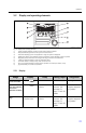
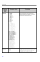
Fig. 9: Display and operating elements
1) Green operating indicator, lights up when supply voltage is applied
2) Red fault indicator, flashes in event of sensor or device error
3) Limit value display: if power is supplied to a relay, the symbol is displayed.
4) Digital input status: green indicates ready for operation, yellow indicates a signal is present
5) Bar graph yellow, 42-section with orange/red range overshoot and undershoot
6) 7-digit 14-segment display in white for measured values
7) 9x77 DOT matrix in white for text, units and menu icons
8) Key or lock symbol indicates whether device operation is locked (see Section 5.3.3)
9) Jog/shuttle dial for local device operation
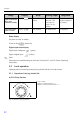
5.2.1 Display
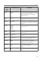
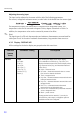
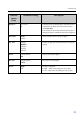
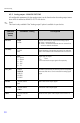
Range Display Relay Analog output Integration
Input current is
< lower error limit
Display " " Fault condition Set failsafe mode No integration
Input current above
lower error limit and
below lower
limitations of validity
Display " " Normal limit value
behavior
Normal behavior
with max. 10%
overrange. No
output < 0 mA/0 V
possible
Normal behavior
(negative integration
not possible)
Input current in valid
range
Display scaled
measured value
Normal limit value
behavior
Normal behavior
with max. 10%
overrange. No
output < 0 mA/0 V
possible
Normal behavior
(negative integration
not possible)