Before using your air conditioner, please read this manual carefully and keep it for future reference. INVERTER ONE-TWO / ONE-THREE /ONE- FOUR/ONE-FIVE SPLIT-TYPE ROOM AIR CONDITIONER MODEL:MMD2-18HDI MMD3-27HDI Please read this installation manual completely before installing the product. If the power cord is damaged, replacement work shall be performed by authorised personnel only. Installation work must be performed in accordance with the national wiring Standards by authorised personnel only.
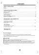
CONTENTS SAFETY PRECAUTIONS Warning ...........................................................................................................................................2 Caution ............................................................................................................................................2 INSTALLATION INSTRUCTIONS Selecting installation place...............................................................................................................
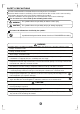
SAFETY PRECAUTIONS Read the follow SAFETY PRECAUTIONS carefully before insta llation . Electrical work must be insta lled b y a licensed elect rician. Be su re to use th e correct rating of the power plug and main circuit for th e mod el to b e inst alled. Incorrect installa tion d ue to ignoring of t he instructio n will cause harm or damage . The seriousn ess is class ified by the following indic ations . WARNING This symbol indicates the possibility of death or serious injury.
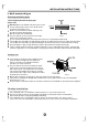
INSTALLATION INSTRUCTIONS 1. Wall -mounted type Selecting installation place Read completely, then follow step by step. Indoor unit Do not e xpos e the indoor unit to heat or steam. S elect a place where there are no obstacle s in front or aro und th e unit. Make sure tha t con densa tion d rainag e can be convenien tly rou ted away. Do not install near a doorway. Fi g.1 E nsure that th e spa ce on the le ft and right of the u nit is more than 12cm.
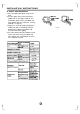
INSTALLATION INSTRUCTIONS Tools needed for installation: Level ga uge Screwdriver Ele ctric drill,Hole co re dril l (φ65 mm) Flaring tool se t Sp ecified torqu e wre nches : 1.8kgf.m, 4.2kg f.m, 5.5kgf.m, 6.6k gf.m(d iffere nt dep endin g on model No.
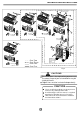
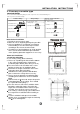
INSTALLATION INSTRUCTIONS 2 More than 15cm 1 3 4 Remote c ontroller 5 Remote Remote control ler controller Remote contr oller 6 Air out A C B Remote c ontroller Loop a connective cable One-Two One-Three One-Four One-Five Fig.3 CAUTIONS This illustration is for explanation purposes only. The actual shape of your air condtioner may be slightly different. Copper lines must be insulated independently CAUTION Use a stud finder to locate studs to prevent unnecessary damage to the wall.
INSTALLATION INSTRUCTIONS Indoor unit installation(wall-mounted type) Cor rect orientatio n of Installat ion Pla te 1. Fit the Installation Plate 1. Fit th e installatio n plate horizontally on structural parts of the wall with spaces aro und the inst allation plate. 2. If the wall is made of br ick, concret e or the like, drill eight (8 ) 5mm diameter holes in the wall. Insert Clip a nchor for appropriate mounting screws. 3. Fit th e installatio n plate on the wall with eight (8) type “A” s crews. F ig.
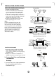
INSTALLATION INSTRUCTIONS 2. When connecting extension drain hose, insulate the connecting part of extension drain hose with a shield pipe, do not let the drain hose slack. Connective pipe installation Fig.8 1. For the left-hand and right-hand piping, remove the pipe cover from the side panel. 2. For the rear-right-hand and rear-left-hand piping, install the piping as shown in Fig.10. Rear-right piping Right-hand piping 3. Fix the end of the connective pipe.
INSTALLATION INSTRUCTIONS 4. Indoor unit installation 1. Pass the piping through the hole in the wall. 2. Put the upper claw at the back of the indoor unit on the upper hook of the installation plate, move the indoor unit from side to side to see that it is securely hooked (see Fig.12). 3. Piping can easily be made by lifting the indoor unit with a cushioning material between the indoor unit and the wall. Get it out after finish piping. 4.
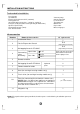
INSTALLATION INSTRUCTIONS 2. Four-wa y casse tte type Attached fittings Please check whether the following fittings are of full scope. If there are some attached fittings free from use, please restore them carefully. Installation Fittings 1. Expansible hook.................................4 Remote controller & Its Frame Tubing & Fittings (on some models) 6. Connecting pipe group.........................1 7. Binding tape.........................................6 9. Remote controller.....................
INSTALLATION INSTRUCTIONS A The length could be calculated from Fig.17: Length=210+L(in general, L is half of the whole length of the installation hook) c. Please adjust the hexangular nuts on the four installation hooks evenly, to ensure the balance of the body. Use the transparent hose filled with water to check the lever of the main body from the four sides or diagonal line direction, the lever indicator also can check the lever from four sides of the main body .(Refer to Fig.
INSTALLATION INSTRUCTIONS (2) Install the panel a. Align the swing motor on the panel to the water receiver of the body properly. (Refer to Fig.23) b. Hang the four fixed rope of the main body to the installation cover and the other three covers of the swing motor: (Refer to Fig.23 ) Drain side 1 Steel rope 2 CAUTIONS: 3 Swing motor installation cover The installation cover of the swing motor must sink into the corresponding water receiver. c.
INSTALLATION INSTRUCTIONS 3. Duct & Ceiling type Installation precautions 1. Determine the moving route. 2. Move the unit in original state. 3. Make sure to do electric insulation according to relevant electric standard in case the unit is installed on metal part of building. 4. Please keep away from the following places, or malfunction may be caused. (if unavoidable, please consult the professionals): A. There is mineral oil like the oil of cutting machine. B. There is much salty air. (Near the coast) C.
INSTALLATION INSTRUCTIONS Installation of unit Install φ 10 (4 pieces)hanging screw bolt Determine the location of hanging screw bolt following Fig.33. Make sure to use the hanging screw bolt of φ10. The treatment to the ceiling varies from construction; please consult the professionals for details. 1) Treatment to ceiling---make sure to consolidate the roof beam for possible vibration to keep the ceiling horizontal. 2) Please cut off the roof beam.
INSTALLATION INSTRUCTIONS 380 The position of hanging bolts 220 175 A B Water outlet,Φ2 5 Refrigerant piping joint ( gas side ) Refrigerant piping joint (gas side) Air outlet sketch map B 148 Air outlet (on side) Φ100 Fresh air inlet Ceiling A 25 C D >500mm >500mm Fig.33 A B C D 915 870 715 870 >12000Btu/h 1260 1224 1015 1215 MODEL <12000Btu/h Air-in grille Air inlet Fig.
INSTALLATION INSTRUCTIONS C AUTIO N 1.5m~2m Supporting Unit The drain pipe as well as the connection part of indoor unit must be heat insulated, or condensate will occur. Please connect the pipe with horny PVC bond and make sure there is no leakage. Do not impose the pressure on connecting part of drainpipe. The gradient downwards of drain pipe should be over 1/100, and do not bend the drain pipe. Pull the drain pipe transversely within 20m.
INSTALLATION INSTRUCTIONS 4. Ceiling and Floor type 4.1 Accessories Name of Acce ssories Q'ty Qutline Remote Controller & Its Frame (on some models) Usage O wner's manual 1 InstallatiOn manual 1 Hook 2 For wall mounting instal lation Hanging ar m 2 For ceiling installation Magnetic ring 1 For wire connetion 1. Remote controller..................1 (This manual) 2. Frame...................................1 3. Mounting screw (ST2.9x10-C-H).....................2 4..
INSTALLATION INSTRUCTIONS 4.2 Indoor unit inst allation 4. For original concrete bricks Use embedd ing screw bold, crock a nd st ick ha rness (Refe r to Fi g.42-4). 1. Installing 10 hanging screw bolts (4 bolts). Please refer to the following figure for the distance measurement between the screw bolts. Please install with 10 hanging screw bolts. The handling to the ceiling varies from the constructions, consult the construction personnels for the specific procedures.
INSTALLATION INSTRUCTIONS 1. Fix the ho ok with tapping screw o nto th e wall. (Ref er to Fig.42 -7) 2. Han g the indoo r unit on the hook. 2. Loc ation the ha nging arm on the hang ing screw bo lt. (Re fer to Fig.4 2-10) Pre pare the mountin g bolt s on th e unit. (Re fer to Fig.42 -11) 8-13mm Screw nut Washer Hook Hanging screw bolt Hanging arm Tapping screw Mounting bolt (Max.40mm) Fig.42 -11 Fig.42-10 Washer 3. Ha ng the unit o n the hangi ng arm by slid ing backwa rd.
INSTALLATION INSTRUCTIONS . Th is man ual is subje ct to change s due to technolo gical i mprovemen t with out further n otices . 4.5 The Dimension of the Unit Unit:mm Capacity 12-18 A B C 990 660 206 D 505 F E 506 G H 907 200 Mou ntin g sc rew B ST2 .9x1 0-C -H 203 SET TEMPERATURE( O C) Note:The dimension of 12000Btu/h and 18000Btu/h are the same. FA N HIGH MED LOW AUTO COOL DRY HE AT TEMP. M ODE S WI NG 5.
INSTALLATION INSTRUCTIONS Hang the ind oor u nit on the ho ok. (The b ottom of bo dy can touch with floor or sus pende d, but the b ody must install vertica lly. ) CAUTION Keep indoor unit, outdoor unit, power supply wiring and transmission wiring at least 1 meter away from televisions and radios. This is to prevent image interference and noise in those electrical appliances. (Noise may be generated depending on the conditions under which the electric wave is generated, even if 1 meter is kept.) Fig.
INSTALLATION INSTRUCTIONS 1. D rill a hole in the wall (su itable just f or the size of the wall con duit), then s et on the f ittings such as the wall conduit and its cover. 2. B ind th e connectin g pipe and the cables t ogether tightly wit h bind ing tapes. P ass t he bou nd co nnect ing pi pe thro ugh t he wall conduct from outside. Be carefu l of the p ipe allocatio n to d o on d amag e to th e t ubing. 3. C onnect the pipes. Refer to "How to Connect the pipes" for details. 4.
INSTALLATION INSTRUCTIONS When the declivity of the drain pipe downwards is over 1/100, there should not be any winding. The total length of the drain pipe when pulled out traversely shall not exceed 20m, when the pipe is over long, a prop stand must be installed to prevent winding. Refer to the figures on the right for the installation of the pipes. Be sure to locate the power wiring and the signal wring well to avoid cross-disturbance.
INSTALLATION INSTRUCTIONS Outdoor unit installation Outdoor installation precaution Install the outdoor unit on a rigid base to prevent increasing noise level and vibration. Determine the air outlet direction where the discharged air is not blocked. In the case that the installation place is exposed to strong wind such as a seaside, make sure the fan operating properly by putting the unit lengthwise along the wall or using a dust or shield plates.
REFRIGERANT PIPE CONNECTION Drain joint installation NOTE: The drain joint differ from appliance to appliance. Fit the seal into the drain joint, then insert the drain joint into the base pan hole of outdoor unit, 。 rotate 90 to securely assemble them. Connecting the drain joint with an extension drain hose (Locally purchased), in case of the water draining off the outdoor unit during the heating mode.
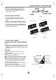
ELECTRICAL WORK D: Flaring work Firmly hold copper pipe in a die in the dimension shown in the table below. Handle Bar Bar Outer diam. (mm) 6.35 9.53 12.7 Yoke A(mm) Max. Min. 1.3 1.6 1.8 0.7 1.0 Cone Copper pipe Clamp handle 1.0 Red arrow mark Fig.5 0 Tightening Connection Align the center of the pipes. Sufficiently tighten the flare nut with fingers, and then tighten it with a spanner and torque wrench as shown in Fig.51 & 52. Outer diam. Flare nut Pipings F ig.
ELECTRICAL WORK Wiring connection Minimum no rmin al cross-se ctional are a of con ducto rs: NOTE: Before performing any electrical work, turn off the main power to the system. R ate d cu rren t of appliance Nominal cro ss-sect iona l 2 ( A) are a (m m ) CAUTIONS 0.75 >3 and <6 Do n ot tou ch the capacitor e ven if you have disco nnect ed the powe r for t here is still high voltage powe r on it, or ele ctric shoc k hazard ma y occur.
AIR PURGING After the confirmation of the above conditions, prepare the wiring as follows: 1) Never fail to have an individual power circuit specifically for the air conditioner. As for the method of wiring, be guided by the circuit diagram posted on the inside of control cover. 2) The screw which fasten the wiring in the casing of electrical fittings are liable to come loose from vibrations to which the unit is subjected during the course of transportation.
AIR PURGING When relocate the unit to another place, perform evacuation using vacuum pump. Make sure the refrigerant added into the air conditioner is liquid form in any case. (Not applicable to the units adopt freon R22 ) Refrigerant Outdoor unit Indoor unit A Gas side C Liquid side D Caution in h andli ng th e packed valve Open the valve stem until it hits against the stopper. Do not try to open it further. Securely tighten the valve stem cap with a spanner or the like.
AIR PURGING Safety and leakage check ● Elec trical safet y check Perform the electric safe check after completing installation: 1. Insulated resistance The insulated resistance must be more than 2MΩ. 2. Grounding work After finishing grounding work, measure the grounding resistance by visual detection and grounding resistance tester. Make sure the grounding resistance is less than 4Ω . 3.
TEST RUNNING Test running Perform test operation after completing gas leak check at the flare nut connections and electrical safety check. Check that all tubing and wiring have been properly connected. Check that the gas and liquid side service valves are fully open. 1. Connect the power, press the ON/OFF button on the remote controller to turn the unit on. 2. Use the MODE button to select COOL, HEAT, AUTO and FAN to check if all the functions works well. 3.
The design and specifications are subject to change without prior notice for product improvement. Consult with the sales agency or manufacturer for details.