LE AVAILAB USER GUIDE 6613_OMU_2+2S_URT_V100 Firmware Description Document November 9, 2011 Rev. 1.
6613_OMU_2+2S_URT_V1_00 Firmware Description Document UG_6613_060 Maxim cannot assume responsibility for use of any circuitry other than circuitry entirely embodied in a Maxim product. No circuit patent licenses are implied. Maxim reserves the right to change the circuitry and specifications without notice at any time. Maxim Integrated Products, 120 San Gabriel Drive, Sunnyvale, CA 94086 408- 737-7600 2011 Maxim Integrated Products Maxim is a registered trademark of Maxim Integrated Products.
UG_6613_ 060 6613_OMU_2+2S_URT_V1_00 Firmware Description Document Table of Contents 1 Introduction ......................................................................................................................................... 5 2 Measurement Description .................................................................................................................. 6 2.1 Basic Measurement Equations ............................................................................................
6613_OMU_2+2S_URT_V1_00 Firmware Description Document UG_6613_060 Tables Table 1: Measurement Equations Definitions ............................................................................................... 6 Table 2: Outlet 1 MPU Outputs ................................................................................................................... 20 Table 3: Outlet 2 MPU Outputs ...................................................................................................................
UG_6613_ 060 6613_OMU_2+2S_URT_V1_00 Firmware Description Document 1 Introduction This document describes the 6613_OMU_2+2S_URT_v100 firmware, which is used with the Teridian 78M6613 power and energy measurement IC. This firmware provides simple methods for calibration and access to measurement data such as Instantaneous Power, Voltage, Current, Power Factor, and Line Frequency.
613_OMU_2+2S_URT_V1_00 Firmware Description Document UG_6613_060 2 Measurement Description 2.1 Basic Measurement Equations The Teridian 78M6613 with firmware 6613_OMU_2+2S_URT_v100 provides the user with measurement data referred to as “Wideband” (WB). Wideband measurements are generally of interest when measuring non-sinusoidal current/voltage, a typical condition in switched mode power supplies or similar systems.
UG_6613_ 060 6613_OMU_2+2S_URT_V1_00 Firmware Description Document 4 Command Line Interface The 6613_OMU_2+2S_URT_v100 firmware implements an instruction set called the Command Line Interface (CLI), which facilitates communication via UART between the 78M6613 and the host processor. 4.1 Identification and Information Commands The I command is used to identify the revisions of the 6613_OMU_2+2S_URT_v100 firmware code and the embedded CE code.
6613_OMU_2+2S_URT_V1_00 Firmware Description Document UG_6613_060 4.3 MPU Data Access Command All the measurement calculations are stored in the MPU data addresses of the 78M6613. The host requests measurement information using the MPU data access command which is a right parenthesis ) To request information, the host sends the MPU data access command, the address (in hex) which is requested, the format in which the data is desired (Hex or Decimal) and a carriage return.
UG_6613_ 060 4.3.3 6613_OMU_2+2S_URT_V1_00 Firmware Description Document Block Reads The block read command can also be used to read consecutive registers: )saddr:eaddr? For decimal format or )saddr:eaddr$ for hex format where saddr is the start address and eaddr is the final address. The following block read command requests the information contained in Table 2 in decimal format: >)20:3D? 4.3.4 Concatenated Reads Multiple commands can also be added on a single line.
6613_OMU_2+2S_URT_V1_00 Firmware Description Document Examples: 10 UG_6613_060 )U Updates the default values of the MPU Data permanently in the flash. )08$ Reads data word at MPU address location 0x08 in hex format. )08$$ Reads data words at MPU address location 0x08, 0x09 in hex format. )08$$$ Reads data words at MPU address location 0x08, 0x09, 0x0A in hex format. )28:4D$ Read data words in hex. )08? Reads data word at MPU address location 0x08 in decimal format.
UG_6613_ 060 6613_OMU_2+2S_URT_V1_00 Firmware Description Document 4.4 Auxiliary Commands 4.4.1 Repeat Command The repeat command can be useful for monitoring measurements and is efficient in demands from the host.
6613_OMU_2+2S_URT_V1_00 Firmware Description Document UG_6613_060 4.5 Calibration Commands Using the precision source method, the user provides a precision voltage and precision current load to the device for calibration. The 6613_OMU_2+2S_URT_v100 firmware provides commands to calibrate the measurement units. For linear current sensors, such as current shunt, no phase calibration is necessary. There are two types of calibration commands. The first type provides complete calibration.
UG_6613_ 060 6613_OMU_2+2S_URT_V1_00 Firmware Description Document 4.5.1.2 CALW Command The CALW command calibrates the temperature, voltage, and power (instead of the current). To calibrate channel 1, enter the following: >CALW or CALW1 The response is: TCal OK VCal OK: WCal 1 OK: > To calibrate channel 2, enter the CAL2 command: >CALW2 The response is: TCal OK VCal OK: WCal 2 OK: > The device calibrates the temperature, the voltage, and the power and save all values to flash.
6613_OMU_2+2S_URT_V1_00 Firmware Description Document 4.5.2 UG_6613_060 Atomic Calibration Commands The atomic calibration commands provide individual calibration of: • Voltage. • Current. • Phase. • Temperature. • Power. A sequence of these commands results in full calibration of the unit. 4.5.2.1 CLV Command The CLV atomic calibration command calibrates voltage to the target value and tolerance and saves the coefficients to flash.
UG_6613_ 060 6613_OMU_2+2S_URT_V1_00 Firmware Description Document The CLP2 command performs the phase calibration for channel 2. The CLP3 command performs the phase calibration for both channel 1 and channel 2. 4.5.2.4 CLT Command The CLT command is used for the temperature calibration. This command adjusts the Temperature Nominal at MPU location 0xA6, saves to flash and initiates temperature gain compensation. The CLT command example is given below: >CLT The response is: TCal OK > 4.5.2.
6613_OMU_2+2S_URT_V1_00 Firmware Description Document 4.6 UG_6613_060 Relay Control Command Relay control is supported by the TC command. The TC command can be used to open (0) or close (1) circuit of all 2 channels. All necessary Sequence (time between each channel), Energized (for closing circuit), and De-Energized (for opening circuit) delay times are set up and used by the library using the following default values: Energized delay time = De-Energized delay time = Sequence delay time = 4.6.
UG_6613_ 060 6613_OMU_2+2S_URT_V1_00 Firmware Description Document 4.7 CE Data Access Commands The CE is the main signal processing unit in the 78M6613. The user writes to the CE data space are mainly for calibration purposes. For the advanced user, details of CE data access commands are described. The commands similar to the MPU access except that ] is used for the CE data access command.
6613_OMU_2+2S_URT_V1_00 Firmware Description Document UG_6613_060 The U command is used for updating default values of the CE Data permanently in the flash. Before issuing the U command, CE must first be turned off by the disable CE command. An example of a U command is as follows: >CE0 >]U Additional examples of CE Data Access commands are provided in the following table: ] CE Data Access Description: Allows user to read from and write to CE data space.
UG_6613_ 060 6613_OMU_2+2S_URT_V1_00 Firmware Description Document The commands that follow are included for reference only. 4.8 CE Control Commands The most pertinent command is the CE enable command, CEn. It is mainly used to turn the CE on or off. The CE is normally enabled but in order to update the CE data entry to flash, the CE must first be turned off using the CE0 command. 4.8.1 Disable CE Command The CE can be disabled by using the following command: >CE0 4.8.
6613_OMU_2+2S_URT_V1_00 Firmware Description Document UG_6613_060 5 MPU Measurement Outputs This section describes the measurement outputs that can be obtained in Manual CLI Mode. Energy outputs are accumulated numbers. The host accessing the measurement information from the 78M6613 more frequently than the accumulation interval will not result in any update in the information. Table 2 lists the wideband measurement outputs for outlet1 and table 3 for outlet 2.
UG_6613_ 060 Output 6613_OMU_2+2S_URT_V1_00 Firmware Description Document Location (hex) LSB Comment Example Bit 20: Reserved. Bit 21: CREEP A Alert – Creep Alert on Outlet 1. Bit 22: CREEP B Alert – Creep Alert on Outlet 2. Bit 23: Line/Neutral Reversal detected. Only available in nonisolated mode (CESTATE, Bit 2=1) Bit 24 –31: Reserved. Irms A Overcurrent Event Count Rev. 1.1 23 Counter increments on each edge event.
6613_OMU_2+2S_URT_V1_00 Firmware Description Document Output Location (hex) LSB Comment Vrms Under Voltage Event Count 24 Counter increments on each edge event. Vrms Over Voltage Event Count 25 Counter increments on each edge event. Vrms A 26 mV Vrms voltage Watts A 27 mW Active power measurement (per second). Wh A 28 mWh Active accumulated energy measurement (per hour). Total Cost A 29 mUnits Cost of Wh A. Irms A 2A mA rms current measurement.
UG_6613_ 060 6613_OMU_2+2S_URT_V1_00 Firmware Description Document Output Location (hex) LSB Comment Reserved 2F – Reserved Vrms A Min 30 mV Minimum Vrms measured Vrms A Max 31 mV Maximum Vrms measured Watts A Min 32 mW Minimum active power measured (per second) Watts A Max 33 mW Maximum active power measured (per second) Irms A Min 34 mArms Minimum rms current measured. Irms A Max 35 mArms Maximum rms current measured.
6613_OMU_2+2S_URT_V1_00 Firmware Description Document Output Location (hex) LSB Comment UG_6613_060 Example VAs A Max 39 mW Maximum apparent power measured (per second). Power Factor A Min 3A – Minimum power factor measured. Minimum is defined as the most negative or least positive number. Power Factor A Max 3B – Maximum power factor measured. Maximum is defined as the most positive or least negative number. Phase Angle A Min 3C – Minimum phase angle measured.
UG_6613_ 060 6613_OMU_2+2S_URT_V1_00 Firmware Description Document Table 3: Outlet 2 MPU Outputs Output Location (hex) LSB Comment Delta Temperature 60 0.1 °C Temperature difference from 22° C. Line Frequency 61 0.01 Hz Line Frequency Example If external temperature is 32 °C )60? Returns: +10.0 If the line frequency is 60 Hz: )61? Returns: +60.00 Definition for Status Register Alarm Status Rev. 1.1 62 Alarms become “1” when thresholds exceeded. Bit 0: Minimum Temperature Alarm.
6613_OMU_2+2S_URT_V1_00 Firmware Description Document Output Location (hex) LSB Comment Counter increments on each edge event. Irms B Overcurrent Event Count 63 Vrms Under Voltage Event Count 64 Counter increments on each edge event. Vrms Over Voltage Event Count 65 Counter increments on each edge event. Vrms B 66 mV Vrms voltage Watts B 67 mW Active power measurement (per second). Wh B 68 mWh Active accumulated energy measurement (per hour). Total Cost B 69 mUnits Cost of Wh B.
UG_6613_ 060 6613_OMU_2+2S_URT_V1_00 Firmware Description Document Output Location (hex) LSB Comment Reserved 6F – Reserved Vrms B Min 70 mV Minimum Vrms measured Vrms B Max 71 mV Maximum Vrms measured Watts B Min 72 mW Minimum active power measured (per second) Watts B Max 73 mW Maximum active power measured (per second) Irms B Min 74 mArms Minimum rms current measured. Irms B Max 75 mArms Maximum rms current measured.
6613_OMU_2+2S_URT_V1_00 Firmware Description Document Output Location (hex) LSB Comment UG_6613_060 Example VAs B Max 79 mW Maximum apparent power measured (per second). Power Factor B Min 7A – Minimum power factor measured. Minimum is defined as the most negative or least positive number. Power Factor B Max 7B – Maximum power factor measured. Maximum is defined as the most positive or least negative number. Phase Angle B Min 7C – Minimum phase angle measured.
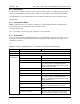
UG_6613_ 060 6613_OMU_2+2S_URT_V1_00 Firmware Description Document 6 Configuration Parameter Entry 6.1 MPU Parameters Table 4 lists the MPU parameters configurable by the 6613_OMU_2+2S_URT_v100 Firmware. Table 4: MPU Parameters MPU Parameter VMAX Location (hex) A0 LSB mVrms Default Comment +471.500 External rms voltage corresponding to 250 mVpk at the VA input of the 78M6613. It must be set high enough to account for overvoltages. Usually set to 471.500 V (471.500d). +0.
6613_OMU_2+2S_URT_V1_00 Firmware Description Document MPU Parameter Location (hex) LSB Default UG_6613_060 Comment Example Temp _raw_x is obtained from the CE: ]71? This value is then entered here: )A6=+value in decimal Also, the command: >CLT Will do the same as the steps above. Temperature Nominal A6 – +0 Temp_raw_x reading at 22 °C. Needed to enable temperature compensation. Reserved A7 – – Reserved PPMC A8 ppm/°C -668 ppm per °C. Do not change the default setting.
UG_6613_ 060 Reserved 6613_OMU_2+2S_URT_V1_00 Firmware Description Document B0 - BC – Additional Status BD – Unused BE – 0 Reserved 1 Bit 0 – Reserved. Bit 1 – WPULSE Disable. Bit 2 – VCal Failure. Bit 3 – ICal1 Failure. Bit 4 – WCal1 Failure. If the tolerance to the target phase is desired to be more coarse, to within 0.5°, the user can enter the following: >)BF=+0.500 Reserved Tolerance on Phase BF 0.001° 0.
6613_OMU_2+2S_URT_V1_00 Firmware Description Document Max Iteration for Voltage Max Iteration for Current 32 C8 C9 1 1 +10 +10 UG_6613_060 Number of attempts to reach the target value (Calibration Voltage entry) within the programmed tolerance.
UG_6613_ 060 MPU Parameter Tolerance on Watts Average Count for Watts 6613_OMU_2+2S_URT_V1_00 Firmware Description Document Location (hex) CA CB LSB mW 1 Default Comment Example +0.010 Measured value to fall within this set tolerance of the target value (Calibration Voltage multiplied by the calibration current entries) for the calibration to be complete. If the tolerance to the target power is desired to be more coarse, to within 0.1W, the user can enter the following: >)CA=+0.
6613_OMU_2+2S_URT_V1_00 Firmware Description Document MPU Parameter Frequency Minimum Threshold Frequency Maximum Threshold SAG Voltage Alarm Threshold Min Voltage Alarm Threshold Location (hex) D2 D3 D4 D5 LSB 0.01Hz 0.01Hz mVpk mVrms Default Comment +59.00 Minimum Frequency Alarm Threshold. A frequency below this threshold will set the alarm (bit 2 of the Alarm Status Register). +61.00 Maximum Frequency Alarm Threshold.
UG_6613_ 060 6613_OMU_2+2S_URT_V1_00 Firmware Description Document MPU Parameter Location (hex) LSB Unused DA - DB – PFA_ Neg Threshold PFA_ Pos Threshold DC DD – – Default Comment Example -0.700 Power Factor Negative Threshold. A less negative power factor than this threshold will set an alarm (bit 11 of the Alarm Status Register). Only available if )F2 bit 2 is set to 1. If the negative power factor threshold is to be changed from the default to -0.6 then set as follows: +0.
6613_OMU_2+2S_URT_V1_00 Firmware Description Document UG_6613_060 6.2 CE Parameters Table 5 lists the CE parameters configurable by the 6613_OMU_2+2S_URT_v100 Firmware. The user does not need to alter any of these parameters. Table 5: CE Parameters CE Parameter CAL IA CAL IB CAL VA CAL VB PHASE_ ADJ_IA PHASE_ ADJ_IB 36 Location (hex) LSB 08 16384 is the default and is a gain of 1. 32767 is max giving a gain of 2. Default +13873 Comment Example Gain constant for IA input.
UG_6613_ 060 CE Parameter CESTATE 6613_OMU_2+2S_URT_V1_00 Firmware Description Document Location (hex) 0E LSB Default 5005h Comment Example SAG CNT Bits 15:8 – determines the consecutive voltage samples below SAG_Threshold before a sag alarm is declared. 255 is the maximum value. Current Sensor Configuration Bit 7 0 use IA for current 1 use I0 - I1for current. Dual Voltage Bit 6 1-VB is separate from VA.
6613_OMU_2+2S_URT_V1_00 Firmware Description Document CE Parameter Location (hex) LSB WRATE 0F Kh = VMAX A * IMAX A / (WRATE * X) 1.6826E+0 1 WattSec Reserved 10 Reserved 11 VMAX A *4.2551E07 (Vpk) +168225 The voltage threshold for SAG warnings. The default value is 80 Vpk if VMAX = 600 V. 12 VMAX A * IMAX A * 1.8541E10 (Watt) 0 Compensation added to the Watt calculation. Used for compensation at low current levels. Keep below 10000d.
UG_6613_ 060 CE Parameter 6613_OMU_2+2S_URT_V1_00 Firmware Description Document Location (hex) LSB Default Comment 0 IA input compensation added for input noise and truncation in the squaring calculation 2 for I . Used for compensation at low current levels. Keep below 10000d. 2 QUANT IA 16 (IMAX A) * 4.6351E-11 2 (A ) QUANT IB 17 (IMAX B) * 4.6351E-11 2 (A ) 0 IA input compensation added for input noise and truncation in the squaring calculation 2 for I .
6613_OMU_2+2S_URT_V1_00 Firmware Description Document UG_6613_060 7 Address Content Summary If the color shading is the same, the information in the table cells is the same between narrowband and wideband measurements. Note that Outlet 1 = channel A and Outlet 2 = channel B.
UG_6613_ 060 6613_OMU_2+2S_URT_V1_00 Firmware Description Document Outlet 2 Common Data Common, Outlet 2 Specific Data Tier 1, Outlet 2 Specific Data Tier 2, Outlet 2 Specific Max/Min Data Rev. 1.
6613_OMU_2+2S_URT_V1_00 Firmware Description Document Totals of Multiple Outlets Common Total Data Wideband 90 Total Watts 91 Total Energy 92 Total Cost 93 Total Current 94 Total VARs 95 Total VA's 96 Total Over Current Count 97 (Reserved for Future) Common Total Max/Min Data 98 Total Watts Min 99 Total Watts Max Bandwidth Specific Total Max/Min Data 9A Total Current Min 9B Total Current Max 9C Total VAR Min 9D Total VAR Max 9E Total VA Min 9F Total VA Max Bandwidth Speci
UG_6613_ 060 6613_OMU_2+2S_URT_V1_00 Firmware Description Document Table 7: MPU Input Summary Chart Voltage A0 Vmax Current - Outlet 1 A1 Imin (Creep A) - Outlet1 A2 Imax (A) - Outlet1 A3 Imin (Creep B) - Outlet2 A4 Imax (B) - Outlet2 Unused A5 Unused Temperature A6 TEMPERATURE NOMINAL A7 Reserved A8 PPMC A9 PPMC2 Current - Outlet 2 Cost Relay Configuration AA Cost per KWh AB Cost Unit string AC Polarity, Latch type AD Sequence Delay AE Energize Delay AF Denergize Dela
6613_OMU_2+2S_URT_V1_00 Firmware Description Document Voltage D4 SAG Voltage Alarm Threshold D5 Min Voltage Alarm Threshold D6 Max Voltage Alarm Threshold Unused D7 Unused Current - Outlet 1 D8 Reserved D9 Max Current Alarm Threshold (WB) Power Factor - Outlet 1 DA Reserved DB Reserved DC Power Factor Alarm - Threshold (WB) DD Power Factor Alarm + Threshold (WB) DE Reserved DF Max Current Alarm Threshold (WB) E0 Reserved E1 Reserved E2 Power Factor Alarm - Threshold (WB) E3
UG_6613_ 060 6613_OMU_2+2S_URT_V1_00 Firmware Description Document Table 8: CE Input Summary Chart Calibration 08 Calibration Gain IA 09 Calibration Gain IB 0A Calibration Gain VA 0B Calibration Gain VB 0C Phase Adjust IA 0D Phase Adjust IB CE Configuration 0E CE State Pulse Rate 0F WRATE 10 Reserved SAG Threshold 11 SAG Threshold Quantization Corrections 12 Quantization offset Watts A 13 Quantization offset Watts B 14 Quantization offset VAR A 15 Quantization offset VAR B
6613_OMU_2+2S_URT_V1_00 Firmware Description Document UG_6613_060 Document Revision History Version Date History 1.0 1/14/2011 First publication. 1.1 11/9/2011 Changed the CESTATE parameter default from 5001h to 5005h. 46 Rev. 1.