
Manual


UG_6613_ 060 6613_OMU_2+2S_URT_V1_00 Firmware Description Document
Rev. 1.1 25
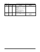
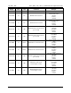
Table 3: Outlet 2 MPU Outputs
Output
Location
(hex)
LSB Comment Example
Delta
Temperature
60 0.1 °C
Temperature difference from 22° C.
If external temperature is 32 °C
)60?<CR>
Returns:
+10.0
Line
Frequency
61 0.01 Hz Line Frequency
If the line frequency is 60 Hz:
)61?<CR>
Returns:
+60.00
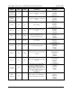
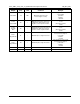
Alarm Status 62
Definition for Status Register
Bit 0: Minimum Temperature Alarm.
Bit 1: Maximum Temperature Alarm.
Bit 2: Minimum Frequency Alarm.
Bit 3: Maximum Frequency Alarm.
Bit 4: SAG Voltage Alarm.
Bit 5: MINVA – under minimum
voltage on VA input.
Bit 6: MAXVA
– over maximum
voltage on VA input.
Bit 7: Reserved.
Bit 8: MAXIA WB
– maximum WB
current exceeded on outlet 1.
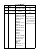
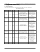
Bit 9: Reserved.
Bit 10: Reserved.
Bit 11: PFA negative WB
– Power
Factor Negative Threshold Alarm.
Only available if )F2 bit 2 is 1.
Bit 12: PFA positive WB
– Power
Factor Positive Threshold Alarm for
outlet 1.
Bit 13: Reserved.
Bit 14: MAXIB_WB
– maximum
wideband current exceeded on
Outlet 2.
Bit 15: Reserved.
Bit 16: Reserved.
Bit 17: PFB_WB negative –
Wideband Power Factor Negative
Threshold Alarm for Outlet 2. Only
available if )F2 bit 2 is 1.
Bit 18: PFB_WB positive
–
Wideband Power Factor Positive
Threshold Alarm for Outlet 2.
Bit 19: MAXIT_WB – maximum total
wideband current exceeded on both
Outlet 1 and Outlet 2.
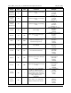
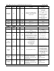
Bit 20: Reserved.
Bit 21: CREEP A Alert – Creep Alert
on Outlet 1.
Bit 22: CREEP B Alert – Creep Alert
on Outlet 2.
Bit 23: Line/Neutral Reversal
detected. Only available in non-
isolated mode (CESTATE, Bit 2=1)
Bit 24 –31: Reserved.
Alarms become “1” when
thresholds exceeded.
Note: Additional Status Alert is
Located at addr 0xBD (see Table 4)
Note: When AC voltage input is less
than or equal to 10 V
RMS
,
• Only MINVA alarm is active.
• All measurements are forced
to 0 except power factor,
which is forced to 1.
Note: The frequency measurement
is forced to 0 as long as the SAG
voltage alarm is active.