
User guide

UG_6613_ 040 6613_PSU_1+1S_URT_V1_00 Firmware Description Document
Rev. 1.0 5
1 Introduction
This document describes the 6613_PSU_1+1S_URT_v1_00 firmware, which is used with the Teridian
78M6613 power and energy measurement IC. This firmware provides simple methods for calibration and
access to measurement data such as Instantaneous Power, Voltage, Current, Power Factor, and Line
Frequency. It is specifically optimized for measurement in single phase AC Power Supplies and
appliances with the following key features:
• Optimized for using current shunt resistors with analog input A0 configured as single-ended Voltage
input and input A1 configured as single-ended Current input. Inputs A2 and A3 unused.
• Phase error calibration routine included for maintaining accuracy over non-ideal power factors
(optional).
• Accumulation or averaging intervals based on fixed number of AC-cycles for compliance with latest
PMBus1.2 recommendations.
• Low-latency SAG status pin for sub-cycle AC fault detection.
• Dual mode host interface (Auto-Reporting or Command Line Interface).
All measurement calculations are computed by the 78M6613 and communicated to the host processor
over a serial interface (UART0) on the TX and RX pins of the 78M6613 device. Digital IOs utilized by this
firmware include:
• DIO17 is a SAG status pin updated every MUX cycle.
• DIO14 is a configurable alarm pin updated every accumulation interval.
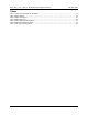
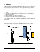
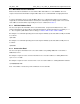
Figure 1 shows a simplified connection diagram of the 78M6613 (emulator connections, decoupling
capacitors and 3.3VDC power supply are omitted in this diagram).
Shunt
NEUTRAL
LINE
A0
A3
750
1M 1M
1000pF
A1
1000pF
A2
LOAD
750
78M6613
V3P3
1
4
3
2
INLET
17
DIO14, 17
SAG, ALARM
6
XIN
XOUT
8
GNDA
GND
V3P3D
V3P3A
23
31
16
32
V3P3
TX
RX
UART_TX14
19
UART_RX
Figure 1: 78M6613 Simplified Connection Diagram for 6613_PSU_1+1S_URT_v1_00 Firmware