
User guide


6613_PSU_1+1S_URT_V1_00 Firmware Description Document UG_6613_040
6 Rev. 1.0
2 Measurement Description
2.1 Basic Measurement Equations
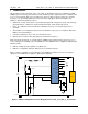
The Teridian 78M6613 with firmware 6613_PSU_1+1S_URT_v1_00 provides the user with measurement
data referred to as “Wideband” (WB). Wideband measurements are generally of interest when measuring
non-sinusoidal current/voltage, a typical condition in switched mode power supplies or similar systems.
Table 1: Measurement Equations Definitions
Symbol Parameter Wideband Equation
V RMS Voltage
V = √∑
v(t)
2
I RMS Current
I = √∑
i(t)
2
P Active Power
P = ∑
(i(t) * v(t))
Q
Reactive
Power
Q = √(S
2
– P
2
)
S
Apparent
Power
S = V * I
PF Power Factor P/S
PA Phase Angle ACOS (P/S)
The measurement outputs are continuously available to the user. To obtain measurement outputs, the
serial UART interface between the 78M6613 and the host processor must be set up and is described in
Section 3.
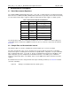
2.2 Sample Rate and Accumulation Interval
This firmware utilizes an effective sampling rate of 6554 samples per second for each input.
The values described in section 2.1 are calculated over a period commonly referred as accumulation
interval. The registers containing the measurements are updated at the completion of every accumulation
time. In firmware 6613_PSU_1+1S_URT_v1_00, the accumulation interval is based on multiples of the
Input Voltage AC cycle. For example if the accumulation interval is set to 30AC cycles, at 50Hz line
frequency, it will result in 20ms * 30 = 600ms. In this case the RMS values will be calculated over 3932
samples.
Accumulation interval can be changed in CLI mode by the following command (see Section 6 for details
of the CLI commands):
> ]18=+30 (Changes accumulation interval to 30 AC cycles)