
Datasheet


71M6xxx Data Sheet
3
List of Figures
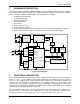
Figure 1: Block Diagram ................................................................................................................................ 4
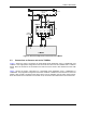
Figure 2: External Components Connected to the 71M6xxx ........................................................................ 7
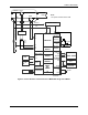
Figure 3: Current Sensors Connected to the 71M6541D/F Using One 71M6x01 ........................................ 8
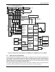
Figure 4: Current Sensors Connected to the 71M6543F/H or 71M6545/H with Three 71M6xx3 ................. 9
Figure 5: Copper Separation and Signal Traces for a Polyphase PCB ...................................................... 10
Figure 6: Wh Error at Room Temperature (71M6203, 100A/0.1A, 60Hz/240V AC) ................................... 15
Figure 7: VARh Error at Room Temperature (71M6203, 100A/0.1A, 60Hz/240V AC) ............................... 15
Figure 8: SOIC-8 Package Outline ............................................................................................................. 16
Figure 9: Pinout for 8-Pin SO Package ....................................................................................................... 17
List of Tables
Table 1: Remote Interface Commands ......................................................................................................... 5
Table 2: Product Variations ........................................................................................................................... 6
Table 3: Absolute Maximum Ratings .......................................................................................................... 11
Table 4: Recommended External Components .......................................................................................... 11
Table 5: Recommended Operating Conditions ........................................................................................... 11
Table 6: Supply Current Performance Specifications ................................................................................. 12
Table 7: Timing Specifications for Power and Data Pulses ........................................................................ 12
Table 8: VCC Voltage Monitor Specifications ............................................................................................. 12
Table 9: Temperature Sensor Specifications .............................................................................................. 12
Table 10: VREF Performance Specifications .............................................................................................. 13
Table 11: ADC Converter Specifications .................................................................................................... 14
Table 12: Pin Description ............................................................................................................................ 17
Table 13: Product Variations ....................................................................................................................... 18
Table 14: Packaging Information, Corresponding CE Codes, and Ordering Numbers .............................. 18