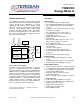
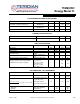
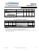
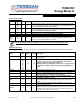
9-5361; Rev 7/11 71M6515H Energy Meter IC A Maxim Integrated Products Brand DATA SHEET JULY 2011 FEATURES The 71M6515H is a high-accuracy analog front-end (AFE) IC that provides measurements for 3-quadrant 3-phase metering. The combination of a 21-bit sigma-delta A/D converter with a six-input analog front-end, a thermally compensated high-precision reference, and a compute engine results in high accuracy and wide dynamic range. Our Single Converter Technology® reduces cross talk and cost.
VREF PULSEW PULSER V3P3A GNDA GNDA ∆Σ ADC CONVERTER IA VA IB VB IC VC GNDD MUX VOLT REG V3P3A + V3P3D 21 GNDD VREF VX TEMP VREF GNDD V2P5 MUXSYNC 2.5V to logic VBIAS (1.
71M6515H Energy Meter IC A Maxim Integrated Products Brand DATA SHEET JULY 2011 ABSOLUTE MAXIMUM RATINGS Supplies and Ground Pins: V3P3D, V3P3A |V3P3D – V3P3A| VBAT GNDD Analog Output Pins: −0.5V to 4.6V 0V to 0.5V -0.5V to 4.6V -0.5V to +0.5V -1mA to 1mA, -0.5V to V3P3A+0.5V -1mA to 1mA, -0.5 to 3.0V VREF V2P5 Analog Input Pins: IA, VA, IB, VB, IC, VC VFLT, VX XIN, XOUT Digital Input Pins: RX D0…D7 All other pins -0.5V to V3P3A+1.0V -0.5V to V3P3A+0.5V -0.5V to 3.0V -0.5V to 3.6V -0.5V to 6V -0.
71M6515H Energy Meter IC A Maxim Integrated Products Brand DATA SHEET JULY 2011 LOGIC LEVELS PARAMETER CONDITION Digital high-level input voltage, VIH Digital low-level input voltage, VIL ILOAD = 1mA ILOAD = 15mA ILOAD = 1mA ILOAD = 15mA VIN=0V Input pull-up current, IIL RESETZ E_RXTX, E_ISYNC/BRKRQ E_RST Other digital inputs Input pull down current, IIH TEST Other digital inputs 1 TYP 2 −0.3 V3P3D –0.4 V3P3D0.
71M6515H Energy Meter IC A Maxim Integrated Products Brand DATA SHEET JULY 2011 PARAMETER CONDITION MIN MAX VREF output voltage, VNOM(25) VREF output impedance VNOM definition 2 Ta = 25ºC 1.193 1.195 1.197 ILOAD = 10µA, -10µA 2.
71M6515H Energy Meter IC A Maxim Integrated Products Brand DATA SHEET JULY 2011 2.5V VOLTAGE REGULATOR PARAMETER CONDITION Reduce V3P3 until V2P5 drops 200mV RESETZ=1, ILOAD=0 Voltage Overhead V3P3D-V2P5 PSRR MIN ΔV2P5/ΔV3P3D TYP -3 MAX UNIT 440 mV +3 mV/V RTC PARAMETER CONDITION Range for date MIN TYP MAX UNIT 2000 -- 2255 year MIN TYP MAX UNIT 11 µs µs RESETZ PARAMETER CONDITION Reset pulse width Reset pulse fall time 1 5 Guaranteed by design; not production tested.
1M6515H Energy Meter IC A Maxim Integrated Products Brand DATA SHEET JULY 2011 PULSE GENERATOR TIMING SPECIFICATIONS PARAMETER CONDITION MIN TYP MAX UNIT 7.56 kHz 0.15 kHz 0.15 kHz CONDITION VALUE UNIT Air velocity 0 m/s. Part soldered to PCB. 63.
71M6515H Energy Meter IC A Maxim Integrated Products Brand DATA SHEET JULY 2011 Temperature Coefficient of Input Impedance LSB size Digital Full Scale ADC Gain Error vs. %Power Supply Variation Vin=65Hz Ω/°C 355 +884736 nV/LSB LSB Vin=200mV pk, 65Hz V3P3A=3.0V, 3.6V 10 6 ∆Nout PK 357nV / VIN 100 ∆V 3P3 A / 3.3 Input Offset (Vin-V3P3A) 1 1.7 -10 50 PPM/ % +10 mV Guaranteed by design; not production tested.
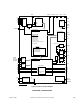
71M6515H Energy Meter IC A Maxim Integrated Products Brand DATA SHEET JULY 2011 VB V3P3A GNDA 50 49 53 VC VA 54 51 IC 55 52 IA IB 56 VX VREF 57 VFLT 59 58 XIN GNDA 61 60 XOUT GNDD 62 RESERVED 64 63 PIN CONFIGURATION AND PIN FUNCTION GNDD 1 48 GNDD RESERVED TMUXOUT /RTM TX 2 47 RESETZ 3 46 V2P5 45 VBAT 44 RX SSCLK 5 CKTEST 6 V3P3D 7 SSDATA SFR TERIDIAN 4 71M6515H-IGT Or 71M6515H-IGTW 8 9 43 RESERVED 42 D0 41 IRQZ 40 PULSE_INIT 39 D6 10 RESERV
71M6515H Energy Meter IC A Maxim Integrated Products Brand DATA SHEET JULY 2011 Analog Pin Description IA, IB, IC VA, VB, VC VFLT VX VREF Pin No. 56 55 54 53 52 51 59 58 57 XIN, XOUT 61 63 Name Type Circuit I 6 I 6 I I I/O 7 6 9 I 8 Description Line Current Sense Inputs: Voltage inputs to the internal A/D converter. Typically, they are connected to the output of a current transformer. The input is referenced to V3P3A. Unused pins must be tied to V3P3A.
71M6515H Energy Meter IC A Maxim Integrated Products Brand DATA SHEET JULY 2011 Name Pin No. Type Circuit UARTCSZ 34 I 3 SRDY SFR SSCLK SSDATA 24 9 5 8 I O O O 3 4 4 4 RX 44 I 3 TX TMUXOUT PULSER PULSEW 4 3 36 35 O O O O 4 4 4 4 Description Enables the UART when 0. The UART is disabled when this pin is set to 1. A positive pulse on this pin will reset the UART. This pin must be terminated to ground. High-Speed Synchronous Interface (SSI). The SRDY input should be tied to ground.
71M6515H Energy Meter IC A Maxim Integrated Products Brand DATA SHEET JULY 2011 I/O Equivalent Circuits V3P3D V3P3A V3P3D V3P3D 110K Digital Input Pin CMOS Input Analog Input Pin To MUX from internal reference V2P5 Pin GNDD GNDA Digital Input Equivalent Circuit Type 1: Standard Digital Input or pin configured as DIO Input with Internal Pull-Up GNDD Analog Input Equivalent Circuit Type 6: ADC Input V2P5 Equivalent Circuit Type 10: V2P5 V3P3D V3P3A Digital Input Pin CMOS Input 110K GNDD Compar
71M6515H Energy Meter IC A Maxim Integrated Products Brand DATA SHEET JULY 2011 %Error TYPICAL PERFORMANCE CHARACTERISTICS 0.2 0.15 0.1 0.05 0 -0.05 -0.1 -0.15 -0.2 0 Deg 60 Deg -60 Deg 180 Deg 1 3 0.3 200 10 0.1 1 25 30 10 100 100 A 1000 Figure 3: Wh Accuracy, 0.3A - 200A/240V 0.2 90 Deg 0.15 150 Deg 0.1 % Error 0.05 3 0 270 Deg 10 25 1 30 0.3 100 -0.05 200 -0.1 -0.15 -0.2 0.1 1 10 A 100 1000 Figure 4: VARh Accuracy for 0.
71M6515H Energy Meter IC A Maxim Integrated Products Brand DATA SHEET JULY 2011 2 1 0 Error [%] -1 -2 -3 50Hz Harmonic Data 60Hz Harmonic Data -4 -5 -6 -7 -8 1 3 5 7 9 11 13 15 17 19 21 23 25 Harmonic Measured at current distortion amplitude of 40% and voltage distortion amplitude of 10%. Figure 5: Meter Accuracy over Harmonics at 240V, 30A Error [%] Performance for Apparent Energy (VAh) 0.2 0.15 0.1 0.05 0 -0.05 -0.1 -0.15 -0.2 0.
71M6515H Energy Meter IC A Maxim Integrated Products Brand DATA SHEET JULY 2011 FUNCTIONAL DESCRIPTION THEORY OF OPERATION The 71M6515H integrates the primary functional blocks required to implement a solid-state electricity meter front end. Included on-chip are an analog front end (AFE), a digital computation engine (CE), a voltage reference, a real time clock, and I/O pins.
71M6515H Energy Meter IC A Maxim Integrated Products Brand DATA SHEET JULY 2011 EQU Element Output Mapping Watt & VAR Formula (WSUM/VARSUM) W0SUM/ VAR0SUM W1SUM/ VAR1SUM W2SUM/ VAR2SUM I0SQ SUM I1SQ SUM I2SQ SUM VA*IA - - IA - - VA*(IA-IB)/2 VA*IB - IA-IB IB - 0 VA IA (1 element, 2W 1φ) 1 VA*(IA-IB)/2 (1 element, 3W 1φ) 2 VA*IA + VB*IB (2 element, 3W 3φ Delta) VA*IA VB*IB - IA IB - 3 VA*(IA-IB)/2 + VC*IC (2 element, 4W 3φ Delta) VA*(IA-IB)/2 - VC*IC IA-IB IB IC 4
71M6515H Energy Meter IC A Maxim Integrated Products Brand DATA SHEET JULY 2011 The minimum combined cycle time for CE and post-processor is 400ms, which makes the maximum frequency for the IRQZ signal 2.5Hz. If the 71M6515H is interfacing to an external DSP (typically, but not necessarily through the SSI interface), the host may turn off post-processing by setting the CE_ONLY bit in the CONFIG word. This will permit setting SUM_CYCLES below its recommended lower limit of 24.
71M6515H Energy Meter IC A Maxim Integrated Products Brand DATA SHEET JULY 2011 Internal data is pulsed out during the accumulation interval immediately following its accumulation interval. Post-processed values are pulsed out one accumulation interval after that. The pulse generator output rate depends on its input value, WRATE, PULSE_SLOW, and PULSE_FAST. Additionally, its maximum pulse width (negative going pulse) is controlled by PULSEWIDTH.
71M6515H Energy Meter IC A Maxim Integrated Products Brand DATA SHEET JULY 2011 The pin PULSE_INIT determines the logic level applied to the pulse pins on power-up, i.e. with PULSE_INIT low, the pulse pins will be initialized to low (default = 1). The pulse width PW is controlled with the PULSEWIDTH register for the PULSER and PULSEW output pins per the following formula: PW = 2 ⋅ PULSEWIDTH + 1 2520.6 The PULSE3 and PULSE4 output pins will always generate pulses with 50% duty cycle.
71M6515H Energy Meter IC A Maxim Integrated Products Brand DATA SHEET JULY 2011 Internal Resources Oscillator The oscillator drives a standard 32.768kHz watch crystal. Crystals of this type are accurate and do not require a high current oscillator circuit. The 71M6515H oscillator has been designed specifically to handle watch crystals and is compatible with their high impedance and limited power handling capability.
71M6515H Energy Meter IC A Maxim Integrated Products Brand DATA SHEET JULY 2011 L W S B M S B L S B M S B L S B M S B L S B M S B RX register address most significant data byte length least significant data byte time TX Figure 9: UART Write Operation UART Read Register Operation The registers are read by sending a byte, consisting of a start register address in the seven MSBs and ‘1’ in the LSB indicating this is a read operation. It is followed by a one byte length of bytes to read.
71M6515H Energy Meter IC A Maxim Integrated Products Brand DATA SHEET JULY 2011 The SSI timing is shown in Figure 11. If 16bit fields If SSI_CKGATE =1 If 32bit fields If SSI_CKGATE =1 SFR (Output) SCLK (Output) 31 SSDATA (Output) 30 16 15 1 0 31 30 SSI_BEG 16 15 1 SSI_BEG+1 0 1 31 0 SSI_END MUX_STATE Figure 11: SSI Timing (SSI_FPOL = SSI_RDYPOL = 0) Fault and Reset Behavior Reset Mode When RESETZ is pulled low or when VFLT < V3P3/2, all activity (i.e.
71M6515H Energy Meter IC A Maxim Integrated Products Brand DATA SHEET JULY 2011 Temperature Compensation for Energy Measurements TEMP_NOM is one of the calibration parameters that must be loaded by the host in order to enable temperature measurement and thereby temperature compensation. PPMC and PPMC2, the linear and quadratic compensation coefficients, compensate for temperature drift in the 71M6515H reference that affects the meter performance.
A Maxim Integrated Products Brand 71M6515H Energy Meter IC DATA SHEET JULY 2011 Name CAL_IA CAL_VA CAL_IB CAL_VB CAL_IC CAL_VC TEMP_NOM PHADJ_A PHADJ_B PHADJ_C Description Gain factors for current and voltage of each phase. The value of TEMP_RAW at nominal temperature. Phase compensation for each current. If phase compensation is 0 or if current sensors have predictable phase, PHADJ may not need to be measured on every meter.
71M6515H Energy Meter IC A Maxim Integrated Products Brand DATA SHEET JULY 2011 General Notes on Calibration The calibration procedures described below should be followed after interfacing the voltage and current sensors to the 71M6515H chip. When properly interfaced, the V3P3 power supply is connected to the meter neutral and is the DC reference for each input. Each voltage and current waveform, as seen by the 6515H, is scaled to be less than 250mV (peak).
A Maxim Integrated Products Brand 71M6515H Energy Meter IC DATA SHEET JULY 2011 Calibration with Three Measurements The simplest calibration method is to make three measurements. Typically, a voltage measurement and two Watt-hour (Wh) measurements are made. If the voltage measurement has the error EV and the two Wh measurements have errors E0 and E60, where E0 is measured with φL = 0 and E60 is measured with φL = 60. These values should be simple ratios—not percentage values.
71M6515H Energy Meter IC A Maxim Integrated Products Brand DATA SHEET JULY 2011 We calculate PHADJ from φS, the desired phase lag: [ ] tan(φ S ) 1 + (1 − 2 −9 ) 2 − 2(1 − 2 −9 ) cos(2πf 0T ) PHADJ = 2 20 −9 −9 (1 − 2 ) sin( 2πf 0T ) − tan(φ S ) 1 − (1 − 2 ) cos(2πf 0T ) [ ] Finally, we calculate the new calibration current gain coefficient, including compensation for a slight gain increase in the phase calibration circuit.
71M6515H Energy Meter IC A Maxim Integrated Products Brand DATA SHEET JULY 2011 Subtract 8 from 7: 9. E 60 − E300 = 2 AXV AXI tan(60) sin(φ S ) use equation 5: E 0 + E180 + 2 tan(60) sin(φ S ) cos(φ S ) 10. E 60 − E300 = 11. E 60 − E300 = ( E 0 + E180 + 2) tan(60) tan(φ S ) ( E 60 − E300 ) 12.
A Maxim Integrated Products Brand 71M6515H Energy Meter IC DATA SHEET JULY 2011 For details on calibrating a meter for Rogowski coil sensors, see the TERIDIAN Application Note AN_6515_036. Meter Design - Scaling of Measured Values An actual meter will always use sensors that scale the voltages and currents managed by the meter to small voltages that can be processed by the 71M6515H. This scaling is reflected in the system parameters VMAX and IMAX.
71M6515H Energy Meter IC A Maxim Integrated Products Brand DATA SHEET JULY 2011 Registers in Alphabetical Order Address (hex) R/W Default APULSEW APULSER APULSE3 APULSE4 0x30 0x31 0x32 0x33 R/W R/W R/W R/W 0 0 0 0 CAL_IA CAL_VA 0x24 0x25 R/W R/W 2 14 2 CAL_IB CAL_VB 0x26 0x27 R/W R/W 2 14 2 Calibration CAL_IC CAL_VC 0x28 0x29 R/W R/W 214 14 2 Calibration CE_DATA 0x63 R/W N/A Control of Basic Functions CE_DATA_ADDR 0x61 R/W N/A Control of Basic Functions CE_DATA_INC 0x65 R
71M6515H Energy Meter IC A Maxim Integrated Products Brand DATA SHEET JULY 2011 Address (hex) R/W Default PHADJ_A PHADJ_B PHADJ_C 0x2A 0x2B 0x2C R/W R/W R/W CT: 0 CT: 0 CT: 0 PPMC1_2 0x1B R/W 0 PULSE3_4_ CNTS 0x42 R N/A PULSE_SRCS 0x43 R/W PULSEW_R_ CNTS 0x41 R N/A Outputs PULSE_WIDTH 0x34 R/W 50 Pulse Generation Control QUANT_W QUANT_VAR QUANT_I 0x36 0x37 0x38 R/W R/W R/W 0 0 0 Calibration RTC_DATE 0x20 R/W N/A RTC_TIME_DAY 0x1F R/W N/A Time RTM 0x21 R/W 0 Te
71M6515H Energy Meter IC A Maxim Integrated Products Brand DATA SHEET JULY 2011 Address (hex) R/W Default Group VPHASE_ABC 0x10 R N/A Outputs VRMS_A VRMS_B VRMS_C 0x09 0x0A 0x0B R R R N/A N/A N/A Outputs WH_A WH_B WH_C 0x00 0x01 0x02 R R R N/A N/A N/A Outputs WRATE 0x2D R/W 683 Name Uses the postprocessor Pulse Generation Control Y_DEG0 0x18 R/W 0 Temperature Compensation Y_DEG1_2 0x19 R/W 0 Temperature Compensation Page: 32 of 60 Comment © 2005−2011 Teridian Semicond
71M6515H Energy Meter IC A Maxim Integrated Products Brand DATA SHEET JULY 2011 Individual Register Descriptions Registers for Pulse Generation Control APULSEW (0x30), APULSER (0x31), APULSE3 (0x32), APULSE4 (0x33), Figure 14 shows the registers that control the PULSEW, PULSER, PULSE3 and PULSE4 output pins if the corresponding PULSE_SRCS register contains the decimal value 36.
A Maxim Integrated Products Brand 71M6515H Energy Meter IC DATA SHEET JULY 2011 At high pulse rates, duty cycle is 50%. At rates less than 1/(2*PWmax), the negative going pulse width is PWmax. The 31 allowed range is 0 to 2 -1. The pulse width for the PULSE3 and PULSE4 outputs is always at a 50% duty cycle. The initial voltage level of the pulse pins is defined with the PULSE_INIT pin.
71M6515H Energy Meter IC A Maxim Integrated Products Brand DATA SHEET JULY 2011 Value in Pulse Source Register (hex) (dec) 0x10 16 0x11 17 0x12 18 0x13 19 0x14 20 0x15 21 0x16 22 Name VASQSUM VBSQSUM VCSQSUM WSUM_I WASUM_I WBSUM_I WCSUM_I 0x17 23 VARSUM_I 0x18 0x19 0x1A 0x1B 0x1C 0x1D 0x1E 24 25 26 27 28 29 30 VARASUM_I VARBSUM_I VARCSUM_I WSUM_E WASUM_E WBSUM_E WCSUM_E 0x1F 31 VARSUM_E 0x20 0x21 0x22 32 33 34 VARASUM_E VARBSUM_E VARCSUM_E 0x23 35 Internal (CE) 0x24 36 External (host)
71M6515H Energy Meter IC A Maxim Integrated Products Brand DATA SHEET JULY 2011 Registers Used for Calibration CAL_IA (0x24), CAL_VA (0x25), CAL_IB (0x26), CAL_VB (0x27), CAL_IC (0x28), CAL_VC (0x29): These registers adjust the gain for the current and voltage measurements of each phase for the purpose of calibration. The calibration factors have to be stored by the host and written to the registers of the 71M6515H after power-up. The allowed 15 15 range is (2 – 1) to –(2 – 1).
71M6515H Energy Meter IC A Maxim Integrated Products Brand DATA SHEET JULY 2011 Example: For a Wh measurement, an error of +1% was observed at 1A. If VMAX is 600V and IMAX = 208A, and if the measurement was taken at 240V, we determine QUANT_W as follows: 1 240 ⋅1 100 QUANT _ W = − = −18460 600 ⋅ 208 ⋅1.04173 ⋅10 −9 The negative value obtained by the calculation will compensate for the positive error.
71M6515H Energy Meter IC A Maxim Integrated Products Brand DATA SHEET JULY 2011 Bits 13-8: These six bits (SUM_CYCLES) define the length of the accumulation interval τ per the formula: τ= SUM _ CYCLES ⋅ 42 2520.6 Allowed values are 24 (400ms) through 60 (1000ms), unless the post-processor is disabled. Bit 8 is the LSB. It is important to note that the length of the accumulation interval, as determined by SUM_CYCLES, is not an exact multiple of 1000ms.
71M6515H Energy Meter IC A Maxim Integrated Products Brand DATA SHEET JULY 2011 Bits 20-19: These two bits (F_SELECT) select the phase that is to be used for frequency measurement. The frequency will be shown in bits 31-16 of the FREQ_DELTA_T register (and as bit 4 of the STATUS word – in this form as a digitized zero crossing signal).
A Maxim Integrated Products Brand 71M6515H Energy Meter IC DATA SHEET JULY 2011 STATUS (0x14) The four bytes in this register reflect the status of the various measurement functions of the 71M6515H. This register is read only. When a bit in the STMASK register is set, an interrupt (IRQZ) is generated as soon as the corresponding bit in the STATUS register is set. Bit 0: This bit (BOOTUP) signals a request from the 71M6515H to the host to be initialized.
71M6515H Energy Meter IC A Maxim Integrated Products Brand DATA SHEET JULY 2011 STMASK (0x15) The four bytes in this register enable interrupts when the corresponding bit in the STATUS register is set. The default value for STMASK is zero. When a bit in the STMASK register is set, an interrupt (IRQZ) is generated as soon as the corresponding bit in the STATUS register is set. Interrupts indicated by IRQZ do not necessarily have to be synchronized with accumulation intervals.
71M6515H Energy Meter IC A Maxim Integrated Products Brand DATA SHEET JULY 2011 The 71M6515H performs ADC temperature compensation by computing a gain adjustment factor for both the voltage and current samples per the following equation: GAIN_ADJ=16384+floor(1+DELTA_T*PPMC/214+DELTA_T2*PPMC2/223) Changes to PPMC1_2 by the host are only allowed if the DEFAULT_PPM bit in the CONFIG register is zero. If additional temperature compensation by the host, e.g.
71M6515H Energy Meter IC A Maxim Integrated Products Brand DATA SHEET JULY 2011 Counter for the PULSE3 generator Page: 43 of 60 Counter for the PULSE4 generator © 2005−2011 Teridian Semiconductor Corporation 1.
A Maxim Integrated Products Brand 71M6515H Energy Meter IC DATA SHEET JULY 2011 IASQSUM (0x39), IBSQSUM (0x3A), ICSQSUM (0x3B) These registers hold the sum of the squared current samples collected during the previous accumulation interval. The values for IASQSUM, IBSQSUM, and ICSQSUM are provided directly by the CE and are not post-processed. The magnitude of the accumulated samples is determined by: LSB = IMAX 2 9.
A Maxim Integrated Products Brand 71M6515H Energy Meter IC DATA SHEET JULY 2011 Since the RMS calculation involves the post-processor, these registers will not be functional when the CE_ONLY bit in the CONFIG register is set. If higher precision is required, the host must calculate the RMS currents from the values in the IASQSUM, IBSQSUM, and ICSQSUM registers. For even higher precision, the IASQFRACT, IBSQFRACT, ICSQFRACT registers should be used. Example: The register IRMS_C reads the value 2,079,670.
A Maxim Integrated Products Brand 71M6515H Energy Meter IC DATA SHEET JULY 2011 If higher precision is required, the host must calculate the RMS voltages from the values in the VASQSUM, VBSQSUM, and VCSQSUM registers. Example: The register VRMS_B reads the value 425,778,000. Assuming VMAX to be 600V, and using the formula above, we determine the RMS voltage of phase B to: V RMS = 425778000 ⋅ 6.8781 ⋅10 −9 600 = 226.
A Maxim Integrated Products Brand 71M6515H Energy Meter IC DATA SHEET JULY 2011 Bits 31-16: These bits (SAGTHR) hold the voltage threshold that is to be applied for sag detection. The peak voltage must exceed SAGTHR once each SAG_CNT samples in order to prevent a SAG warning. One LSB is defined as: LSB = 7.8798 ⋅ 216 ⋅10 −9 VMAX Example: A meter operating at 50Hz and 240V (RMS) is supposed to apply a sag threshold of 180V (RMS) for at least four periods before a sag warning is issued. VMAX is 600V.
71M6515H Energy Meter IC A Maxim Integrated Products Brand DATA SHEET JULY 2011 LSB = 450.76 ⋅10 −6 VMAX SUM _ CYCLES V rms Example: A meter designed with VMAX=600V and IMAX=208A is supposed to apply an overvoltage threshold of 520V (RMS) and an over-current threshold of 400A (RMS). Which values are to be selected for V_PTHRESHOLD and I_PTHRESHOLD? V _ PTHRESHOLD = 520 520 = = 14,893 LSB 450.76 ⋅ 10 −6 600 SUM _ CYCLES I _ PTHRESHOLD = 400 400 = = 33,046 LSB 450.
71M6515H Energy Meter IC A Maxim Integrated Products Brand DATA SHEET JULY 2011 Bits 15-8:. These bits (RTM2) select the CE address for RTM2. Bits 23-16: These bits (RTM1) select the CE address for RTM1. Bits 31-24: These bits (RTM0) select the CE address for RTM0. SSI (0x22) This register controls the function of the Serial Synchronous Interface (SSI). The function of the SSI is described in the Internal Resources section of this data sheet.
A Maxim Integrated Products Brand 71M6515H Energy Meter IC DATA SHEET JULY 2011 Example: DIO pins D0 through D3 are to be configured as outputs, while D4 through D7 are to be inputs. DIO7 must generate a DEDGE interrupt when the input value changes, and D0 through D3 must apply the hexadecimal pattern 0x05. This makes the selection for the D_CONFIG registers as follows: DIO_INTCTRL = 0x80, D_DIR = 0x0F, DIO_VALUE = 0x05 The values are combined into the 32-bit pattern 0x800F0005.
71M6515H Energy Meter IC A Maxim Integrated Products Brand DATA SHEET JULY 2011 Registers in Numerical Order Address Name Address Name Address Name 0x00 WH_A 0x20 RTC_DATE 0x40 START_THRESHLD 0x01 WH_B 0x21 RTM 0x41 PULSEW_R_CNTS 0x02 WH_C 0x22 SSI 0x42 PULSE3_4_CNTS 0x03 VARH_A 0x23 RESERVED 0x43 PULSE_SRCS 0x04 VARH_B 0x24 CAL_IA 0x44 VFEED_A 0x05 VARH_C 0x25 CAL_VA 0x45 VFEED_B 0x06 VAH_A 0x26 CAL_IB 0x46 VFEED_C 0x07 VAH_B 0x27 CAL_VB 0x47 0x08 VA
71M6515H Energy Meter IC A Maxim Integrated Products Brand DATA SHEET JULY 2011 APPLICATION INFORMATION Meter Circuits Bits 7 through 5 (EQU) of the CONFIG register allow the selection of the metering equation that is to be implemented by the 71M6515H. The equation to be used depends on the meter configuration. Figure 15 shows how the 71M6515H is connected for the most common configuration, the three-phase, four-wire WYE. The neutral wire connects to V3P3A.
71M6515H Energy Meter IC A Maxim Integrated Products Brand DATA SHEET JULY 2011 B LOAD B C A LOAD A IA IB IC V3P3A VC VA VB EQU = 2 P=VA*IA+VB*IB 71M6515H Figure 16: 3-Wire 3-Phase Delta Connection C LOAD C LOAD B B NEUTRAL A LOAD A IA IB IC V3P3A VC VA VB 71M6515H Figure 17: 4-Wire 3-Phase Delta Connection Page: 53 of 60 © 2005−2011 Teridian Semiconductor Corporation 1.
71M6515H Energy Meter IC A Maxim Integrated Products Brand DATA SHEET JULY 2011 Communication between the 71M6515H and the Host Processor General To ensure proper transfer of energy and other values from the 71M6515H to the host, the output data of the 71M6515H must be read by the host each time they are ready, and no energy-related datum can be missed. This requires close synchronization between the 71M6515H and the host.
71M6515H Energy Meter IC A Maxim Integrated Products Brand DATA SHEET JULY 2011 flag in the STATUS register. This happens because the incomplete or garbled data could have included a write command to the CONFIG register or other important registers. Methods of Control Two different methods of control can be used by the host processor: 1) Synchronization using the IRQZ pin of the 71M6515H (interrupt or DIO pin polling method, see Figure 19): a.
71M6515H Energy Meter IC A Maxim Integrated Products Brand DATA SHEET JULY 2011 read commands from host read commands from host 6515H not ready 6515H not ready 6515H data 6515H data post-processor active post-processor active 330ms 330ms 1000ms time 2000ms Figure 20: Timing Diagram (Host Polling) Communication Steps for Interrupt Method: The following is a list of commands required from the host processor to establish communication with the 71M6515H.
71M6515H Energy Meter IC A Maxim Integrated Products Brand DATA SHEET JULY 2011 Timing The fundamental factor for all timing considerations is SUM_CYCLES, which determines the length of the accumulation interval for the 71M6515H per the equation: τ= SUM _ CYCLES ⋅ 42 2520.6 Hz The default setting for SUM_CYCLES is 60, which yields an accumulation interval close to 1,000ms. A conservative minimum number for SUM_CYCLES is 24, which yields an accumulation interval close to 400ms.
71M6515H Energy Meter IC A Maxim Integrated Products Brand DATA SHEET JULY 2011 PACKAGE OUTLINE 11.7 12.3 11.7 + 12.3 PIN No. 1 Indicator 9.8 10.2 0.50 Typ. 0.60 Typ. 0.00 0.20 1.40 1.60 0.14 0.28 NOTE: Controlling dimensions are in mm Ordering Information PART DESCRIPTION ORDER NO.
A Maxim Integrated Products Brand 71M6515H Energy Meter IC DATA SHEET JULY 2011 REVISION HISTORY Revision Rev. 1.0 Rev. 1.1 Date October 26, 2005 December 11, 2006 Rev. 1.2 March 15, 2007 Rev. 1.3 August 17, 2007 Rev. 1.4 March 5, 2008 Page: 59 of 60 Description First publication. Changed capacitor values for XIN/XOUT Corrected addresses for CE_DATA and made addresses CE_DATA etc. visible in table “Registers in Numerical Order”.
A Maxim Integrated Products Brand 71M6515H Energy Meter IC DATA SHEET JULY 2011 Added value for RθJA in Electrical Specification. Rev 1.5 January 18, 2011 Changes for transition to Maxim DC: - Title page: Deleted reference to temperature range in 0.1% Wh accuracy statement. Deleted “Protects accumulated data” under “Battery Backup”. - Deleted reference to “patented” technology - Deleted Figure 6 (Typical Meter Accuracy over Temperature) Added Guaranteed By Design notes to Electrical Specifications.