
Datasheet


71M6521DE/DH/FE Data Sheet
Rev 3 Page: 101 of 107
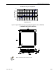
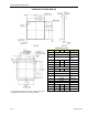
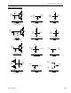
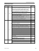
Recommended PCB Land Pattern for the QFN-68 Package
Recommended PCB Land Pattern Dimensions
Symbol Description
Typical
Dimension
e Lead pitch 0.4mm
x Pad width 0.23mm
y Pad length, see note 3 0.8mm
d See note 1 6.3mm
A 6.63mm
G 7.2mm
Note 1: Do not place unmasked vias in region denoted by dimension “d”.
Note 2: Soldering of bottom internal pad is not required for proper operation.
Note 3: The ‘y’ dimension has been elongated to allow for hand soldering and reworking. Production assembly may
allow this dimension to be reduced as long as the ‘G’ dimension is maintained.