
Datasheet


71M6521DE/DH/FE Data Sheet
Rev 3 Page: 43 of 107
EEPROM Interface
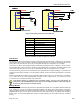
The 71M6521DE/DH/FE provides hardware support for either type of EEPROM interface, a two-pin interface and a
three-pin interface. The interfaces use the EECTRL and EEDATA registers for communication.
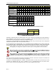
Two-Pin EEPROM Interface
The dedicated 2-pin serial interface communicates with external EEPROM devices. The interface is multiplexed onto
pins DIO4 (SCK) and DIO5 (SDA) controlled by the DIO_EEX bit I/O RAM (see I/O RAM Table). The MPU
communicates with the interface through two SFR registers: EEDATA and EECTRL. If the MPU wishes to write a byte
of data to EEPROM, it places the data in EEDATA and then writes the ‘Transmit’ command (CMD = 0011) to EECTRL.
This initiates the transmit operation. The transmit operation is finished when the BUSY bit falls. Interrupt INT5 is also
asserted when BUSY falls. The MPU can then check the RX_ACK bit to see if the EEPROM acknowledged the
transmission.
A byte is read by writing the ‘Receive’ command (CMD = 0001) to EECTRL and waiting for the BUSY bit to fall. Upon
completion, the received data is in EEDATA. The serial transmit and receive clock is 78kHz during each transmission,
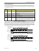
and the clock is held in a high state until the next transmission. The bits in EECTRL are shown in Table 57.
The EEPROM interface can also be operated by controlling the DIO4 and DIO5 pins directly (“bit-banging”).
However, controlling DIO4 and DIO5 directly is discouraged, because it may tie up the MPU to the point
where it may become too busy to process interrupts.
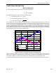
Status
Bit
Name
Read/
Write
Reset
State
Polarity Description
7
ERROR
R
0
Positive
1 when an illegal command is received.
6
BUSY
R
0
Positive
1 when serial data bus is busy.
5
RX_ACK
R
1
Negative
0 indicates that the EEPROM sent an ACK bit.
4
TX_ACK
R
1
Negative
0 indicates when an ACK bit has been sent to the EEPROM
3-0
CMD
[3:0]
W 0
Positive,
see CMD
Table
CMD
Operation
0000
No-op. Applying the no-op command will stop the I
2
C clock
(SCK, DIO4). Failure to issue the no-op command will keep
the SCK signal toggling.
0001
Receive a byte from EEPROM and send ACK.
0011
Transmit a byte to EEPROM.
0101
Issue a ‘STOP’ sequence.
0110
Receive the last byte from EEPROM, do not send ACK.
1001
Issue a ‘START’ sequence.
Others
No Operation, set the ERROR bit.
Table 57: EECTRL Status Bits