71M6541 Demo Board REV 3.0 User’s Manual Rev 4.0; 12/12 Maxim Integrated cannot assume responsibility for use of any circuitry other than circuitry entirely embodied in a Maxim Integrated product. No circuit patent licenses are implied. Maxim Integrated reserves the right to change the circuitry and specifications without notice at any time. Maxim Integrated 160 Rio Robles, San Jose, CA 95134 USA 1-408-601-1000 © 2012 Maxim Integrated Products, Inc.
71M6541 Demo Board REV 3.0 User’s Manual Table of Contents 1 GETTING STARTED................................................................................................................................................ 5 1.1 General .................................................................................................................................................................... 5 1.2 Safety and ESD Notes ....................................................................................
71M6541 Demo Board REV 3.0 User’s Manual 2.3.5 Calibration Procedure with Five Measurements .............................................................................................. 42 2.3.6 Calibration Spreadsheets ................................................................................................................................ 42 2.3.7 Compensating for Non-Linearities ...................................................................................................................
71M6541 Demo Board REV 3.0 User’s Manual Figure 2-19: Shunt with Center Drill Holes ........................................................................................................................ 56 Figure 3-1: 71M6541-DB REV 3.0 - Board Description ..................................................................................................... 61 Figure 4-1: 71M6541-DB REV 3.0 Demo Board: Electrical Schematic 1/2 .......................................................................
71M6541 Demo Board REV 3.0 User’s Manual 1 1 GETTING STARTED 1.1 GENERAL The Maxim Integrated 71M6541-DB REV 3.0 Demo Board is a demonstration board for evaluating the 71M6541 device for single-phase electronic energy metering applications in conjunction with the Remote Sensor Interface. It incorporates a 71M6541 integrated circuit, a 71M6601 Remote Interface IC, peripheral circuitry such as a serial EEPROM, emulator port, and on-board power supply.
71M6541 Demo Board REV 3.0 User’s Manual 1.3 DEMO KIT CONTENTS • • • • • Demo Board D6541 REV 3.0 containing one 71M6601 or 71M6201 Remote Sensor Interface and one 71M6541F IC with pre-loaded demo program 5VDC/1,000mA universal wall transformer with 2.5mm plug (Switchcraft 712A compatible) Serial-USB converter USB cable ANSI base with 50 μΩ shunt resistor (optional, for ANSI kits only) or two 120 μΩ shunt resistors 1.4 DEMO BOARD VERSIONS This manual applies to D6541 REV 3.0 only. 1.
1M6541 Demo Board REV 3.0 User’s Manual 1.7 DEMO BOARD TEST SETUP Figure 1-1 shows the basic connections of the Demo Board plus optional Debug Board with the external equipment. The PC can be connected via the USB Interface (CN1). For stand-alone testing (without AC voltage) the Demo Board maybe powered via the 5.0 VDC input (J20). The optional Debug Board must be powered with its own 5 VDC power supply.
71M6541 Demo Board REV 3.0 User’s Manual 1.7.1 POWER SUPPLY SETUP There are several choices for the meter power supply: o o Internal (using the AC line voltage). The internal power supply is only suitable when the voltage exceeds 100V RMS. To enable the internal supply, a jumper needs to be installed across JP6 on the top of the board. External 5.0VDC connector (J20) on the Demo Board. 1.7.2 CABLES FOR SERIAL COMMUNICATION 1.7.2.
71M6541 Demo Board REV 3.0 User’s Manual 1.7.3 CHECKING OPERATION A few seconds after power up, the LCD display on the Demo Board should display a brief greeting in the top row and the demo code revision in the bottom row: H E L L 5. 4 G 0 The “HELLO” message should be followed by the display of accumulated energy: 0. 0 0 0 Wh SYS 3 The “SYS” symbol will be blinking, indicating activity of the MPU inside the 71M6541.
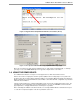
71M6541 Demo Board REV 3.0 User’s Manual Figure 1-2: HyperTerminal Sample Window with Disconnect Button (Arrow) Figure 1-3: Port Speed and Handshake Setup (left) and Port Bit setup (right) Once, the connection to the demo board is established, press and the command prompt, >, should appear. Type >? to see the Demo Code help menu. Type >i to verify the demo code revision. 1.8 USING THE DEMO BOARD The 71M6541 Demo Board is a ready-to-use meter prepared for use with external shunt resistors.
71M6541 Demo Board REV 3.0 User’s Manual 1.8.1 SERIAL COMMAND LANGUAGE The Demo Code residing in the flash memory of the 71M6541 provides a convenient way of examining and modifying key meter parameters via its command line interface (CLI). The tables in this chapter describe the commands in detail. Commands for CE Data Access: ] CE DATA ACCESS Description: Allows user to read from and write to CE data space.
71M6541 Demo Board REV 3.0 User’s Manual Commands for I/O RAM (Configuration RAM) and SFR Control: R I/O RAM AND SFR CONTROL Description: Allows the user to read from and write to DIO RAM and special function registers (SFRs). Usage: R [option] [register] … [option] Command combinations: RIx… Select I/O RAM location x (0x2000 offset is automatically added) Rx… Select internal SFR at address x Ra???... Read consecutive SFR registers in Decimal, starting at address a Ra$$$...
71M6541 Demo Board REV 3.0 User’s Manual Auxiliary Commands: Typing a comma (“,”) repeats the command issued from the previous command line. This is very helpful when examining the value at a certain address over time, such as the CE DRAM address for the temperature (0x40). The slash (“/”) is useful to separate comments from commands when sending macro text files via the serial interface. All characters in a line after the slash are ignored.
71M6541 Demo Board REV 3.0 User’s Manual Commands for Battery Mode Control and Battery Test: B INFORMATION MESSAGES Comment Description: Allows the user to control battery modes and to test the battery. Usage: BL Enters LCD mode when in brownout mode (B> prompt). BS Enters sleep mode when in brownout mode (B> prompt). BT Starts a battery test – when in mission mode (> prompt). BWSn Set wake timer to n seconds for automatic return to brownout mode.
71M6541 Demo Board REV 3.0 User’s Manual Reset Commands: W RESET Description: Watchdog control Usage: W Comment Halts the Demo Code program, thus suppressing the triggering of the hardware watchdog timer. This will cause a reset, if the watchdog timer is enabled. Commands for the 71M6X0X Remote Sensor Interface: 15 6 71M6X0X Interface Comment Description: Commands for control of the Remote Sensor Interface IC. Usage: 6En Remote sensor Enable (1 Enable, 0 Disable) 6Ra.
71M6541 Demo Board REV 3.0 User’s Manual Commands for Controlling the Metering Values Shown on the LCD Display: Step Text or Numerical Display CLI command 0 10000 00 M0 Meter ID 1 24.5 °C 01 M1 Temperature difference from calibration temperature. 2 59.9 02 M2 Frequency at the VA_IN input [Hz] 3 3.27 Whr 03 M3 Accumulated imported real energy [Wh]. The default display setting after power-up or reset. M4 Accumulated exported real energy [Wh]. M5 Accumulated reactive energy [VARh].
71M6541 Demo Board REV 3.0 User’s Manual 1.8.2 USING THE DEMO BOARD FOR ENERGY MEASUREMENTS The 71M6541 Demo Board was designed for use with shunt resistors connected directly to the IAP/IAN pins of the 71M6541 and via the Remote Sensor Interface and it is shipped in this configuration. The Demo Board may immediately be used with a 50 µΩ shunt resistor (ANSI) or a 120 µΩ shunt resistor (IEC). It is programmed for a kh factor of 1.0 (see Section 1.8.
71M6541 Demo Board REV 3.0 User’s Manual overvoltages. This choice need not be of concern, since the ADC in the 71M6541 has enough resolution, even when operating at 120Vrms or 240Vrms. If a different set of voltage-dividers or an external voltage transformer (potential transformer) is to be used, scaling techniques should be used.
71M6541 Demo Board REV 3.0 User’s Manual Table 1-4: CE RAM Locations for Calibration Constants Coefficient CE Address (hex) CAL_VA 0x11 Adjusts the gain of the voltage channels. +16384 is the typical value. The gain is directly proportional to the CAL parameter. Allowed range is 0 to 32767. If the gain is 1% slow, CAL should be increased by 1%. CAL_IA CAL_IB 0x10 0x13 Adjusts the gain of the current channels. +16384 is the typical value. The gain is directly proportional to the CAL parameter.
71M6541 Demo Board REV 3.0 User’s Manual 1.9.4 UPDATING CALIBRATION DATA IN FLASH OR EEPROM It is possible to make data permanent that had been entered temporarily into the CE RAM. The transfer to EEPROM memory is done using the following serial interface command: >]CLS Thus, after transferring calibration data with manual serial interface commands or with a macro file, all that has to be done is invoking the U command. Similarly, calibration data can be restored to default values using the CLD command.
71M6541 Demo Board REV 3.0 User’s Manual Figure 1-5: Emulator Window Showing Reset and Erase Buttons (see Arrows) Figure 1-6: Emulator Window Showing Erased Flash Memory and File Load Menu Flash Programmer Module (TFP-2): The operational firmware of the TFP2 will have to be upgraded to revision 1.53. Follow the instructions given in the User Manual for the TFP-2. 21 Rev 4.
71M6541 Demo Board REV 3.0 User’s Manual 1.9.6 THE PROGRAMMING INTERFACE OF THE 71M6541 Flash Downloader/ICE Interface Signals The signals listed in Table 1-5 are necessary for communication between the Flash Downloader or ICE and the 71M6541.
71M6541 Demo Board REV 3.0 User’s Manual 1.10 DEMO CODE 1.10.1 DEMO CODE DESCRIPTION The Demo Board is shipped preloaded with Demo Code in the 71M6541F chip. The code revision can easily be verified by entering the command >i via the serial interface (see section 1.8.1). Check with your local Maxim Integrated representative or FAE for the latest revision. The Demo Code is provided in two different versions: • Single-phase two-wire operation (EQU 0, with secondary tamper sensor).
71M6541 Demo Board REV 3.0 User’s Manual Table 1-6: MPU XRAM Locations Name Purpose LSB Default )? Signed? Bits i_min Metering element enters creep mode if current is below this value. If 0, creep logic is disabled. In creep mode, on each metering element, Wh, VARh, i0sqsum, and other items are zeroed. Same units as CE’s i0sqsum. 0.08A )0 signed 32 )1 N/A 8 cfg Configure meter operation on the fly. bit0: 1=Display KWh. bit1: 1=clear accumulators, errors, etc. (e.g.
71M6541 Demo Board REV 3.0 User’s Manual v_limit Error if exceeded.* Same units as CE’s v0sqsum. 407.3V = 240V*sqrt(2) *120% )6 signed 32 wrate_mpu Convert from CE counts to pulses. CE’s w0sum units per pulse, rounded up to next largest CE count so Wh accumulation and display is always rounded down. 3.2 Wh for 3phase 1.0 Wh for 1phase )7 signed 32 interval The number of minutes of a demand interval. Count of minutes. (60/interval)*interval = 60. 2 minutes.
71M6541 Demo Board REV 3.0 User’s Manual lcd_idx lcd_bit mfr_id 26 6 Selects LCD’s current display. 0: Meter identification. (“#”) 1: Display variation from calibration temperature, 0.1C 2: Display mains Hz, 0.1 Hz 3: mWh, total 4: mWh total exported. 5: mVARh, total. 6: mVARh, total exported. 7:mVAh, total 8: Operating hours. 9: Time of day 10: Calendar date 11: Power factor, total 12: Angle between phase 0 & 1 13: Main edge count, last accumulation.
71M6541 Demo Board REV 3.0 User’s Manual i_max2 4 in_limit in_wait 3 3 Like i_max, except for the 2nd current sensor. Currents, Wh etc. using currents from the second sensor are rescaled into the same units as the first current sensor. 0.1 Amps 208 A (2080) )1C signed 16 Maximum valid neutral current. Same units as CE’s i3sqsum. 0.1A )1D signed 32 The time that neutral current can exceed n_max before the neutral error is asserted. Count of accumulation intervals. 10 secs.
71M6541 Demo Board REV 3.0 User’s Manual Status of meter. Nonvolatile. Bits: See table below. 0 = no errors )30 wh_im Wh energy register. Nonvolatile. First 32-bit number is a count of pulses, =3.2 Wh in 3-phase meters, or 1 in 1-phase. A fractional pulse is present in the CE data, but not preserved. n/a )31 64 wh_ex Wh exported energy register. Nonvolatile. Like wh_im n/a )32 64 varh_im VARh register. Nonvolatile. Like wh_im n/a )33 64 varh_ex VARh exported register. Nonvolatile.
71M6541 Demo Board REV 3.0 User’s Manual 3 Three-phase ICs only. Some CE codes calculate neutral current rather than measuring it. Consult the CE documentation. 4 Only in systems with two current sensors. 5 High accuracy use of this feature may require a calibrated clock. 6 IEC 62056 Manufacturers’ IDs are allocated by the FLAG Association Limited. Maxim Integrated does not own or profit from the FLAG association. Maxim Integrated’s default id may not conform, and is for demonstration purposes only.
71M6541 Demo Board REV 3.0 User’s Manual 1.10.3 LSB VALUES IN CE REGISTERS Table 1-8: CE Registers and Associated LSB Values Register Name LSB Value W0SUM_X 1.55124*10-12*IMAX*VMAX VAR0SUM_X 1.55124*10-12*IMAX*VMAX W1SUM_X 1.55124*10-12*IMAX*VMAX VAR1SUM_X 1.55124*10-12*IMAX*VMAX I0SQSUM_X 2.55872*10-12*IMAX*VMAX I1SQSUM_X V0SQSUM_X 2.5587*10-12*IMAX*VMAX 9.40448*10-13*IMAX*VMAX V1SQSUM_X 9.
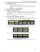
71M6541 Demo Board REV 3.0 User’s Manual Table 1-9: IMAX for Various Shunt Resistance Values and Remote Sensor Types Remote Sensor Interface Rated Current [A] Max. Voltage at IAP/IAN [mV] 71M6601 60 62.5 71M6201 200 17.86 Shunt Resistor Value [µΩ] 500 400 300 250 200 160 120 75 50 25 88.39 110.49 147.31 176.78 220.97 276.21 368.28 IMAX Entry at MPU 0x03 +884 +1105 +1473 +1768 +2209 +2762 +3683 WRATE for kH = 1.
71M6541 Demo Board REV 3.0 User’s Manual Table 1-10: Identification of 71M6X0X Remote Sensor Types Bit 5/Bit 4 71M6X0X Remote Interface Current Range [A] 00 71M6601 or 71M6603 60 01 71M6103 or 71M6113 (Poly-Phase) 100 10 71M6201 or 71M6203 200 11 Invalid -- 1.10.6 COMMUNICATING WITH THE 71M6X0X Some commands are useful to communicate with the 71M6X0X Remote Sensor Interface for the purpose of test and diagnosis. Some useful commands are: 1) 6C1.
71M6541 Demo Board REV 3.0 User’s Manual 33 6) Send the Intel hex file built for operation with the bootloader (e.g., 6541eq0_5p4g_07feb12.hex) using the ‘Send Text File’ command of HyperTerminal. 7) During the load procedure, the Wh LED will blink. Once the load process is completed it stops blinking. The Wh LED should remain on solidly at the completion of the load procedure, which indicates an error-free load. If the LED turns off at the end, an error must have occurred.
71M6541 Demo Board REV 3.0 User’s Manual 2 2 APPLICATION INFORMATION 2.1 SENSOR CONNECTIONS AND EQUATIONS The 71M6541 Demo Board supports the following meter configurations and equations: • Single-phase two-wire (EQU 0) • Single-phase three-wire (EQU 1) Note: Support of EQU 2 requires the 71M6542 IC, which will be available on a separate Demo Board.
71M6541 Demo Board REV 3.0 User’s Manual 2.1.2 SINGLE-PHASE TWO-WIRE (EQU 0) This is the most basic configuration for this Demo Board. The current sensor is connected directly to the IAP/IAN inputs of the 71M6541 (see Figure 2-2). The energy measurement is based on the following equation: P = VA * IA See the explanation below Table 1-8 for the calculation of IMAX. A second current sensor can be connected to the IBP/IBP inputs of the 71M6541, for example to detect tampering (see Figure 2-3).
71M6541 Demo Board REV 3.0 User’s Manual in the primary channel, the CE code allows scaling between the two channels so that all energy calculations can be based on IMAX. 2.1.3 SINGLE-PHASE THREE-WIRE (EQU 1) This meter configuration (see Figure 2-4) is used in North America (ANSI market) and parts of South America. The energy measurement is based on the following equation: P = VA/2 * (IA – IB) Both current sensors can be shunt sensors. The second current sensor may also be a CT.
71M6541 Demo Board REV 3.0 User’s Manual 2.2 CALIBRATION THEORY A typical meter has phase and gain errors as shown by φS, AXI, and AXV in Figure 2-5. Following the typical meter convention of current phase being in the lag direction, the small amount of phase lead in a typical current sensor is represented as -φS. The errors shown in Figure 2-5 represent the sum of all gain and phase errors. They include errors in voltage attenuators, current sensors, and in ADC gains.
71M6541 Demo Board REV 3.0 User’s Manual 3a. AXV AXI [cos(60) cos(φ S ) + sin(60) sin(φ S )] −1 cos(60) E 60 = = AXV AXI cos(φ S ) + AXV AXI tan(60) sin(φ S ) − 1 Combining 2a and 3a: 4. E 60 = E 0 + ( E 0 + 1) tan(60) tan(φ S ) 5. tan(φ S ) = 6. φ S = tan −1 E 60 − E 0 ( E 0 + 1) tan(60) E 60 − E 0 ( E 0 + 1) tan(60) and from 2a: 7.
71M6541 Demo Board REV 3.0 User’s Manual 5. AXV AXI = 6. AXI = E 0 + E180 + 2 2 cos(φ S ) ( E 0 + E180 ) 2 + 1 AXV cos(φ S ) Use above results along with E60 and E300 to calculate φS. 7. E 60 = IV AXV AXI cos(60 − φ S ) −1 IV cos(60) = AXV AXI cos(φ S ) + AXV AXI tan(60) sin(φ S ) − 1 8. E300 = IV AXV AXI cos(−60 − φ S ) −1 IV cos(−60) = AXV AXI cos(φ S ) − AXV AXI tan(60) sin(φ S ) − 1 Subtract 8 from 7 9.
71M6541 Demo Board REV 3.0 User’s Manual 2.3 CALIBRATION PROCEDURES 2.3.1 CALIBRATION EQUIPMENT Calibration requires that a calibration system is used, i.e., equipment that applies accurate voltage, load current and load angle to the unit being calibrated, while measuring the response from the unit being calibrated in a repeatable way. By repeatable we mean that the calibration system is synchronized to the meter being calibrated.
71M6541 Demo Board REV 3.0 User’s Manual The calibration procedures described below should be followed after interfacing the voltage and current sensors to the 71M6541F chip. When properly interfaced, the V3P3 power supply is connected to the meter neutral and is the DC reference for each input. Each voltage and current waveform, as seen by the 71M6541F, is scaled to be less than 250mV (peak). 2.3.4 CALIBRATION PROCEDURE WITH THREE MEASUREMENTS Each phase is calibrated individually.
71M6541 Demo Board REV 3.0 User’s Manual 2.3.5 CALIBRATION PROCEDURE WITH FIVE MEASUREMENTS Each phase is calibrated individually. The calibration procedure is as follows: 1) The calibration factors for all phases are reset to their default values, i.e., CAL_In = CAL_Vn = 16384, and PHADJ_n = 0. 2) An RMS voltage Videal consistent with the meter’s nominal voltage is applied, and the RMS reading Vactual of the meter is recorded.
71M6541 Demo Board REV 3.0 User’s Manual Figure 2-7: Calibration Spreadsheet for Three Measurements 43 Rev 4.
71M6541 Demo Board REV 3.0 User’s Manual Figure 2-8: Calibration Spreadsheet for Five Measurements 44 Rev 4.
71M6541 Demo Board REV 3.0 User’s Manual 2.3.7 COMPENSATING FOR NON-LINEARITIES Nonlinearity is most noticeable at low currents, as shown in Figure 2-9, and can result from input noise and truncation. Nonlinearities can be eliminated using the QUANT variable. 12 error [%] 10 error 8 6 4 2 0 0.1 1 10 100 I [A] Figure 2-9: Non-Linearity Caused by Quantification Noise The error can be seen as the presence of a virtual constant noise current.
71M6541 Demo Board REV 3.0 User’s Manual 2.4 TEMPERATURE COMPENSATION 2.4.1 ERROR SOURCES For a meter to be accurate over temperature, the following major sources of error have to be addressed: 1) The resistance of the shunt sensor(s) over temperature. The temperature coefficient (TC) of a shunt resistor is typically positive (PTC) and can be far higher than the TC of the pure Manganin material used in the shunt. TCs of several hundred PPM/°C have been observed for certain shunt resistors.
71M6541 Demo Board REV 3.
71M6541 Demo Board REV 3.0 User’s Manual 2.4.3 CALCULATING PARAMETERS FOR COMPENSATION 2.4.3.1 Shunt Resistors The TC of the shunt resistors can be characterized using a temperature chamber, a calibrated current, and a voltmeter with filtering capabilities. A few shunt resistors should be measured and their TC should be compared. This type of information can also be obtained from the manufacturer. For sufficient compensation, the TC of the shunt resistors must be repeatable.
71M6541 Demo Board REV 3.0 User’s Manual GAIN_ADJ 16410 16400 GAIN_A… 16390 16380 16370 16360 16350 16340 16330 16320 16310 -40 -20 0 20 40 60 80 Figure 2-10: GAIN_ADJ over Temperature Some curve-fitting is required to find PPMC6X and PPMC26X coefficients that will generate the desired behavior of the GAIN_ADJ register. For this case, PPMC6X = -960 and PPMC26X = -610 approach the curve very accurately.
71M6541 Demo Board REV 3.0 User’s Manual 2.4.3.3 Reference Voltage of the 71M6541 At a later time, it will be shown how the compensation coefficients for the reference voltage of the 71M6541 can be derived. For the moment, let us assume that we know these coefficients, and that they are PPMC4X = -820 and PPMC24X = -680. 2.4.3.
71M6541 Demo Board REV 3.0 User’s Manual For the control of GAIN_ADJB, we will need the following coefficients: CS2: Since we assume that the shunt resistors are very similar with respect to their TC, we use the value found for the shunt connected at phase B (PPMCS = -3331). Again, PPMC2S for the shunt resistor is 0. Since this coefficient applies to the current measurement only, we will have to apply the ½ factor mentioned above. C4X: PPMC4X = -820 and PPMC24X = -680, as already stated above.
Meter under Test AC Voltage Optical Pickup for Pulses Current CT Pulse Counter Calibrated Outputs 71M6541 Demo Board REV 3.0 User’s Manual PC Calibrator Figure 2-12: Meter with Calibration System Figure 2-13 shows the screen on the controlling PC for a typical Demo Board. The error numbers are given in percent. This means that for the measured Demo Board, the sum of all errors resulting from tolerances of PCB components, current sensors, and 71M6541F tolerances was –3.
71M6541 Demo Board REV 3.0 User’s Manual Form 2S - Wh Error [%] at 0°, 60° and 300° Phase Angle, 240 V/60 Hz 0.25 0.20 0.15 0.10 0.05 0.00 60° 300° 0° -0.05 -0.10 -0.15 -0.20 -0.25 0.1 1 10 100 1000 Figure 2-14: Wh Load Lines at Room Temperature with 71M6201 and 50 µΩ Shunts 2.6 SENSORS AND SENSOR PLACEMENT Both sensor self-heating and sensor placement has to be considered in order to avoid side effects that can affect measurement accuracy.
71M6541 Demo Board REV 3.0 User’s Manual The effect of shunt self-heating can be described by the following formulae.
71M6541 Demo Board REV 3.0 User’s Manual 2.6.3 PLACEMENT OF SENSORS (IEC) The arrangement of the current terminals in a typical IEC meter enclosure predetermines the spacing of the shunts, and usually allows for only for 20 to 22 mm center-to-center spacing between the shunts. This means that the clearance between adjacent shunts is typically only 10 mm or less. A typical arrangement is shown in Figure 2-15, left side. This arrangement is not optimized for suppression of cross-talk.
71M6541 Demo Board REV 3.0 User’s Manual 2.6.4 OTHER TECHNIQUES FOR AVOIDING MAGNETIC CROSSTALK With very high currents or close distances between shunt sensors, magnetic pickup or cross-talk will sometimes occur even if good placement practices are followed. One mechanism for cross-talk is shown in Figure 2-17, where the Manganin zone and the sensor wire act as a loop that will generate an output voltage similar to that generated by a Rogowski coil.
71M6541 Demo Board REV 3.0 User’s Manual 57 Rev 4.
71M6541 Demo Board REV 3.0 User’s Manual 3 3 HARDWARE DESCRIPTION 3.1 71M6541-DB DESCRIPTION: JUMPERS, SWITCHES AND TEST POINTS The items described in the following tables refer to the flags in Figure 3-1. 58 Item # Reference Designator Name Use 1 TP2 GND GND test point. 2 JP58 WPULSE 3 D5 Wh 4 D6 VARh 2-pin header connected to the Wh pulse LED Wh pulse LED. VARh pulse LED. Selector for the operation of the IC when main power is removed.
71M6541 Demo Board REV 3.0 User’s Manual Item # Reference Designator Name 13 J21 DEBUG Connector for Debug Board. 2x8 pin male header. 14 SW5 RESET Chip reset switch: When the switch is pressed, the RESET pin of the IC is pulled high which resets the IC into a known state. 15 J12 -- 2-pin header. If a jumper installed, the battery BT1 will be connected to the V3P3SYS net. 16 J13 -- 2-pin pin header. If a jumper installed, the battery BT2/BT3 will be connected to the V3P3SYS net.
71M6541 Demo Board REV 3.0 User’s Manual Item # Reference Designator Name Use SEGDIO51/OPT_TX pin to the LCD. If the second UART is used, the jumper should be removed from the header. 32 J14 EMULATOR I/F 2x10 emulator connector port for the Signum ICE ADM-51 or for the TFP2 Flash Programmer. 33 JP54 E_RXTX Three 2-pin headers that connects the E_RXTX, E_RXTX, and E_TCLK pins to the LCD. The emulator pins should be configured as LCD pins when this jumper is inserted.
71M6541 Demo Board REV 3.0 User’s Manual Figure 3-1: 71M6541-DB REV 3.0 - Board Description (Default jumper settings are indicated in yellow) 61 Rev 4.
71M6541 Demo Board REV 3.0 User’s Manual 3.2 BOARD HARDWARE SPECIFICATIONS PCB Dimensions Width, length Thickness Height w/ components 134 mm x 131 mm (5.276” x 5.157”) 1.6mm (0.062”) 40 mm (1.57”) Environmental Operating Temperature Storage Temperature Power Supply Using internal AC supply DC Input Voltage (powered from DC supply) Supply Current Input Signal Range AC Voltage Signal(VA) AC Current Signals (IA) from Shunt/CT -40°…+85°C -40°C…+100°C 100 V…240 V RMS 5.0 VDC ±0.
71M6541 Demo Board REV 3.0 User’s Manual 63 Rev 4.
71M6541 Demo Board REV 3.0 User’s Manual 4 4 APPENDIX This appendix includes the following documentation, tables, and drawings: 71M6541 Demo Board Description D6541 REV 3.0 Demo Board Electrical Schematic D6541 REV 3.0 Demo Board Bill of Materials D6541 REV 3.0 Demo Board PCB layers (copper, silkscreen, top and bottom side) 71M6541 IC Description 71M6541 Pin Description 71M6541 Pinout 64 Rev 4.
71M6541 Demo Board REV 3.0 User’s Manual 4.1 71M6541-DB ELECTRICAL SCHEMATIC Positive Supply COMBO FOOTPRINT 100uF/15V D3 1N4148WS 0.22uF C8 D15 Power Down Circuit Note: C29, C32, and C34 have been reversed on the silk screen. This schematic is correct! 1 2 3 Q2 BC857 R18 275V 5VDC C32 NEUTRAL_IN JP20 R7 2M 1N4148WS 30K D2 BOARD_SUPPLY SEGDIO8 D7 1N4148WS D13 1N4148WS D14 1N4148WS R20 8.06K U1 C29 1000uF/6V R13 2 1 C13 D10 1N4148WS D11 100uF/15V 1N4148WS 1.
71M6541 Demo Board REV 3.0 User’s Manual V3P3D SEGDIO8 J13 2 1 PB 1K C18 0.1uF R103 10K 2 2 4 6 8 10 HDR5X2 JP8 HDR2X1 R4 SW5 RESET 100 C21 0.1uF R106 1K 1 V3P3D 2 1 * HDR2X1 C28 0.1uF C50 1000pF C62 0.1uF * LED D8 R8 2 U3 1 RX_USB 2 3 GND_USB 4 5 6 7 8 TMUX2OUT TMUXOUT Off-Page Connectors R9 R10 R11 62 62 62 C55 100pF IAP U2 0.
71M6541 Demo Board REV 3.0 User’s Manual 4.2 71M6541-DB BILL OF MATERIAL Table 4-1: 71M6541-DB REV 3.0: Bill of Material Item Q Reference Part Footprint Digi-Key P/N Mouser P/N Manufacturer Manufacturer P/N Tol Rating HDR DNP 1 2 BT1,BT2 BATTERY 2 1 BT3 BATTERY 3 4 5 6 7 1 1 1 3 15 USB-B 15pF 10pF 0.1uF 0.1uF 8 9 1 1 CN1 C1 C2 C3,C7,C27 C4,C18,C19,C20,C21,C22, C28,C33,C51,C56,C60,C62, C64,C67,C68 C5 C6 BAT 3 PIN BARREL COMBO BAT CR2032 MAX USBV 603 603 805 603 0.01uF 4.
71M6541 Demo Board REV 3.0 User’s Manual 45 1 R6 8.20K 46 2 R7,R66 2M 47 48 49 50 51 52 53 54 55 56 57 58 59 60 61 62 63 64 65 3 3 1 1 1 3 1 1 1 1 4 3 4 1 1 2 5 2 2 R8,R106,R142 R9,R10,R11 R12 R13 R14 R15,R16,R17 R18 R19 R20 R21 R22,R26,R55,R57 R23,R32,R56 R24,R25,R33,R34 R27 R39 R47,R64 R74,R76,R103,R104,R105 R84,R85 R86,R87 1K 62 100K 20K 6.04K 62 30K 150 8.06K 25.2K 0 750 3.4 130 4.
71M6541 Demo Board REV 3.0 User’s Manual 4.3 71M6541-DB PCB LAYOUT Figure 4-3: 71M6541-DB REV 3.0: Top View 69 Rev 4.
71M6541 Demo Board REV 3.0 User’s Manual Figure 4-4: 71M6541-DB REV 3.0: Top Copper 70 Rev 4.
M6541 Demo Board REV 3.0 User’s Manual Figure 4-5: 71M6541-DB REV 3.0: Bottom View 71 Rev 4.
71M6541 Demo Board REV 3.0 User’s Manual Figure 4-6: 71M6541-DB REV 3.0: Bottom Copper 72 Rev 4.
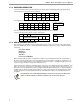
71M6541 Demo Board REV 3.0 User’s Manual 4.4 71M6541 PINOUT INFORMATION Power/Ground/NC Pins: Table 4-2: 71M6541 Pin Description Table 1/3 Name Type GNDA GNDD P P V3P3A P V3P3SYS P V3P3D O VDD O VLCD O VBAT P VBAT_RTC P Description Analog ground: This pin should be connected directly to the ground plane. Digital ground: This pin should be connected directly to the ground plane. Analog power supply: A 3.3 V power supply should be connected to this pin.
71M6541 Demo Board REV 3.0 User’s Manual Digital Pins: Table 4-4: 71M6541 Pin Description Table 3/3 Name Type COM3,COM2, COM1,COM0 O SEGDIO0 … SEGDIO14, SEGDIO19 … SEGDIO25, SEGDIO44, SEGDIO45, I/O SEGDIO26/ COM5, SEGDIO27/ COM4 SEGDIO36/ SPI_CSZ, SEGDIO37/ SPI_DO, SEGDIO38/ SPI_DI, SEGDIO39/ SPI_CKI SEGDIO51/ OPT_TX, SEGDIO55/ OPT_RX E_RXTX/SEG48 E_RST/SEG50 E_TCLK/SEG49 I/O Description LCD Common Outputs: These 4 pins provide the select signals for the LCD display.
64 63 62 61 60 59 58 57 56 55 54 53 52 51 50 49 SPI_CKI/SEGDIO39 SEGDIO44 SEGDIO45 TMUX2OUT/SEG46 TMUXOUT/SEG47 RESET PB VLCD VREF IAP IAN V3P3A VA TEST GNDA XOUT 71M6541 Demo Board REV 3.
71M6541 Demo Board REV 3.0 User’s Manual 4.5 REVISION HISTORY REVISION DATE 2.0 1-14-2010 Initial release based on DBUM revision 1.1 for 6541 REV 1.0 Demo Board. 2.1 1-16-2010 Added Table 1-8 and explanation of scaling in CE and MPU codes. Added cautionary notes for connection of Line and Neutral. Updated formulae for WRATE and kh calculation. 76 DESCRIPTION Updated Figures 2-1, 2-2, and 2-3. Updated CLI tables and Bill of Material. Added chapter on temperature compensation.